Input and output Supervisor mode, exceptions, traps
Input and output Supervisor mode, exceptions, traps. I/O devices. Usually includes some non-digital component Typical digital interface to CPU:. status reg. CPU. mechanism. data reg. Example : 8251 UART.

Input and output Supervisor mode, exceptions, traps
E N D
Presentation Transcript
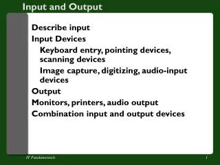
I/O devices • Usually includes some non-digital component • Typical digital interface to CPU: status reg CPU mechanism data reg
Example : 8251 UART • Universal asynchronous receiver transmitter (UART) : provides serial communication • 8251 functions are integrated into standard PC interface chip • Allows many communication parameters to be programmed
Serial communication • Characters are transmitted separately: no char bit 0 bit 1 bit n-1 ... stop start time
Serial communication parameters • Baud (bit) rate • Number of bits per character • Parity/no parity • Even/odd parity • Length of stop bit (1, 1.5, 2 bits)
8251 CPU interface 8251 status (8 bit) CPU xmit/ rcv data (8 bit) serial port
How to communicate with the registers in the interface • Memory-Mapped I/O • Isolated I/O (standard I/O) • Advantages and disadvantages
Programming I/O • Two types of instructions can support I/O • special-purpose I/O instructions • memory-mapped load/store instructions • Intel x86 provides in, out instructions • Most other CPUs use memory-mapped I/O • I/O instructions do not preclude memory-mapped I/O
ARM memory-mapped I/O • Define location for device: DEV1 EQU 0x1000 • Read/write code: LDR r1,#DEV1 ; set up device adrs LDR r0,[r1] ; read DEV1 LDR r0,#8 ; set up value to write STR r0,[r1] ; write value to device
Modes of Transfer • Suppose a peripheral intermittently receives data, which must be serviced by the processor • The processor can poll the peripheral regularly to see if data has arrived – wasteful • The peripheral can interrupt the processor when it has data • Data transfer under program control • Busy-waiting, Polling • Interrupt • DMA transfer
Busy/wait output • Simplest way to program device • Use instructions to test when device is ready current_char = mystring; while (*current_char != ‘\0’) { poke(OUT_CHAR,*current_char); while (peek(OUT_STATUS) != 0); current_char++; }
Interrupt-driven I/O • Busy/wait is very inefficient (Why?) • CPU can’t do other work while testing device • Hard to do simultaneous I/O • Interrupts allow a device to change the flow of control in the CPU • Causes subroutine call to handle device
Interrupt interface • Requires extra pins: Intreq, Intack • If Intreq is 1, processor suspends current program, jumps to an Interrupt Service Routine, or ISR • Known as interrupt-driven I/O • Essentially, “polling” of the interrupt pin is built-into the hardware, so no extra time! intreq status reg CPU intack mechanism IR PC data/address data reg
Interrupt sequence • CPU acknowledges request • Device sends vector • CPU calls ISR • Execution of ISR • CPU restores state to foreground program
Priorities and vectors • Two mechanisms allow us to make interrupts more specific: • Priorities determine what interrupt gets CPU first • Vectors determine what code is called for each type of interrupt • Mechanisms are orthogonal: most CPUs provide both
Interrupts - Vectors • What is the address (interrupt address vector) of the ISR? • Fixed interrupt • Address built into microprocessor, cannot be changed • Either ISR stored at address or a jump to actual ISR stored if not enough bytes available • Vectored interrupt • Peripheral must provide the address • Common when microprocessor has multiple peripherals connected by a system bus • Compromise: interrupt address table
1(a): μP is executing its main program. 1(b): P1 receives input data in a register with address 0x8000. Time 2: P1 asserts Int to request servicing by the microprocessor. 3: After completing instruction at 100, μP sees Int asserted, saves the PC’s value of 100, and asserts Inta. 4: P1 detects Inta and puts interrupt address vector 16 on the data bus. 5(a):μP jumps to the address on the bus (16). The ISR there reads data from 0x8000, modifies the data, and writes the resulting data to 0x8001. 5(b): After being read, P1 deasserts Int. 6: The ISR returns, thus restoring PC to 100+1=101, where μP resumes executing. Interrupt-driven I/O using vectored interrupt
μP Data memory Program memory ISR 16: MOV R0, 0x8000 System bus 17: # modifies R0 18: MOV 0x8001, R0 19: RETI # ISR return ... P1 P2 Inta Main program Int 16 ... PC 100: instruction 0x8000 0x8001 100 101: instruction Interrupt-driven I/O using vectored interrupt 1(a): P is executing its main program 1(b): P1 receives input data in a register with address 0x8000.
μP Data memory Program memory ISR 16: MOV R0, 0x8000 System bus 17: # modifies R0 18: MOV 0x8001, R0 19: RETI # ISR return ... Inta P1 P2 Int Main program 16 ... 1 PC 100: instruction 0x8000 0x8001 100 101: instruction Interrupt-driven I/O using vectored interrupt 2: P1 asserts Int to request servicing by the microprocessor Int
μP Data memory Program memory ISR 16: MOV R0, 0x8000 System bus 17: # modifies R0 18: MOV 0x8001, R0 19: RETI # ISR return 1 ... Inta Inta P1 P2 Int Main program 16 ... PC 100: instruction 0x8000 0x8001 100 100 101: instruction Interrupt-driven I/O using vectored interrupt 3: After completing instruction at 100, μP sees Int asserted, saves the PC’s value of 100, and asserts Inta
μP Data memory Program memory ISR 16: MOV R0, 0x8000 System bus System bus 17: # modifies R0 16 18: MOV 0x8001, R0 19: RETI # ISR return ... Inta P1 P2 Int Main program 16 16 ... PC 100: instruction 0x8000 0x8001 101: instruction Interrupt-driven I/O using vectored interrupt 4: P1 detects Inta and puts interrupt address vector 16 on the data bus 100
μP Data memory Program memory ISR ISR 16: MOV R0, 0x8000 System bus System bus 16: MOV R0, 0x8000 17: # modifies R0 17: # modifies R0 18: MOV 0x8001, R0 18: MOV 0x8001, R0 19: RETI # ISR return ... 19: Inta RETI # ISR return P1 P1 P2 P2 ... Int Int Main program 16 ... Main program 0 PC ... 100: instruction 0x8000 0x8000 0x8001 0x8001 100: instruction 100 101: instruction 101: instruction Interrupt-driven I/O using vectored interrupt 5(a): PC jumps to the address on the bus (16). The ISR there reads data from 0x8000, modifies the data, and writes the resulting data to 0x8001. 5(b): After being read, P1 deasserts Int.
μP Data memory Program memory ISR ISR 16: MOV R0, 0x8000 System bus 16: MOV R0, 0x8000 17: # modifies R0 17: # modifies R0 18: MOV 0x8001, R0 18: MOV 0x8001, R0 19: RETI # ISR return ... 19: RETI # ISR return P1 P2 Int ... Main program ... Main program PC 0x8000 0x8001 ... 100: instruction +1 100: instruction 100 100 100 101: instruction 101: instruction Interrupt-driven I/O using vectored interrupt 6: The ISR returns, thus restoring the PC to 100+1=101, where the μP resumes
Interrupt address table • Compromise between fixed and vectored interrupts • One interrupt pin • Table in memory holding ISR addresses (maybe 256 words) • Peripheral doesn’t provide ISR address, but rather index into table • Fewer bits are sent by the peripheral • Can move ISR location without changing peripheral
Additional interrupt issues • Maskable vs. non-maskable interrupts • Maskable: programmer can set bit that causes processor to ignore interrupt • Important when in the middle of time-critical code • Non-maskable: a separate interrupt pin that can’t be masked • Typically reserved for drastic situations, like power failure requiring immediate backup of data to non-volatile memory • Jump to ISR • Some microprocessors treat jump same as call of any subroutine • Complete state saved (PC, registers) – may take hundreds of cycles • Others only save partial state, like PC only • Thus, ISR must not modify registers, or else must save them first • Assembly-language programmer must be aware of which registers stored
Micro-processor System bus 7 Inta 5 Priority arbiter Peripheral1 Peripheral2 Int 3 2 2 Ireq1 Iack1 6 Ireq2 Iack2 Arbitration: Priority arbiter • Consider the situation where multiple peripherals request service from single resource (e.g., microprocessor, DMA controller) simultaneously - which gets serviced first? • Priorityarbiter • Single-purpose processor • Peripherals make requests to arbiter, arbiter makes requests to resource • Arbiter connected to system bus for configuration only
Micro-processor System bus 7 Inta 5 Priority arbiter Peripheral1 Peripheral2 Int 3 2 2 Ireq1 Iack1 6 Ireq2 Iack2 Arbitration using a priority arbiter • 1. Microprocessor is executing its program. • 2. Peripheral1 needs servicing so asserts Ireq1. Peripheral2 also needs servicing so asserts Ireq2. • 3. Priority arbiter sees at least one Ireq input asserted, so asserts Int. • 4. Microprocessor stops executing its program and stores its state. • 5. Microprocessor asserts Inta. • 6. Priority arbiter asserts Iack1 to acknowledge Peripheral1. • 7. Peripheral1 puts its interrupt address vector on the system bus • 8. Microprocessor jumps to the address of ISR read from data bus, ISR executes and returns • (and completes handshake with arbiter). • 9. Microprocessor resumes executing its program.
Arbitration: Priority arbiter • Types of priority • Fixed priority • each peripheral has unique rank • highest rank chosen first with simultaneous requests • preferred when clear difference in rank between peripherals • Rotating priority (round-robin) • priority changed based on history of servicing • better distribution of servicing especially among peripherals with similar priority demands
P System bus Peripheral1 Peripheral2 Inta Ack_in Ack_out Ack_in Ack_out Int 0 Req_out Req_in Req_out Req_in Daisy-chain aware peripherals Arbitration: Daisy-chain arbitration • Arbitration done by peripherals • Built into peripheral or external logic added • req input and ack output added to each peripheral • Peripherals connected to each other in daisy-chain manner • One peripheral connected to resource, all others connected “upstream” • Peripheral’s req flows “downstream” to resource, resource’s ack flows “upstream” to requesting peripheral • Closest peripheral has highest priority
Micro-processor P System bus System bus Inta Peripheral1 Peripheral2 Priority arbiter Peripheral1 Peripheral2 Inta Int Ack_in Ack_out Ack_in Ack_out Int 0 Req_out Req_in Req_out Req_in Ireq1 Iack1 Ireq2 Daisy-chain aware peripherals Iack2 Arbitration: Daisy-chain arbitration • Pros/cons • Easy to add/remove peripheral - no system redesign needed • Does not support rotating priority • One broken peripheral can cause loss of access to other peripherals
Intel 8259 IR0 IR1 IR2 IR3 IR4 IR5 IR6 IR7 D[7..0] A[0..0] RD WR INT INTA CAS[2..0] SP/EN Intel 8259 programmable priority controller
Sources of interrupt overhead • ISR execution time • Interrupt mechanism overhead • Register save/restore • Pipeline-related penalties • Cache-related penalties
ARM interrupts • ARM7 supports two types of interrupts: • Fast interrupt requests (FIQs) • Interrupt requests (IRQs) • Exception table starts at location 0 • 0xFFFF0000 if high vector address is defined
ARM interrupt procedure • CPU actions: • Save PC. Copy CPSR to SPSR • Force bits in CPSR to record interrupt • Force PC to vector • Handler responsibilities: • Restore proper PC • Restore CPSR from SPSR • Clear interrupt disable flags
6 7 M 0 M 1 M 3 M 2 M 4 T F I N Z C V Q Interrupt request exception • IRQ is generated externally by asserting the IRQ input on the processor • Lower priority than FIQ • I bit : disable IRQ when it is set • F bit: disable FIQ when it is set
IRQ R14_irq = address of next instruction to be executed + 4 SPSR_irq = CPSR CPSR[4:0] = 0b10010 /* enter IRQ mode */ CPSR[5] = 0 /* execute in ARM state */ /*CPSR[6] is unchanged */ CPSR[7] = 1 /* disable normal interrupt */ If high vectors configured then PC = 0xFFFF0018 else PC = 0x00000018 To return SUBS PC, R14, #4 /* PC from R14_irq, CPSR from SPSR_irq */
FIQ R14_fiq= address of next instruction to be executed + 4 SPSR_fiq = CPSR CPSR[4:0] = 0b10001 /* enter FIQ mode */ CPSR[5] = 0 /* execute in ARM state */ CPSR[6] = 1 /* disable fast interrupt */ CPSR[7] = 1 /* disable normal interrupt */ If high vectors configured then PC = 0xFFFF001C else PC = 0x0000001C To return SUBS PC, R14, #4 /* PC from R14_fiq, CPSR from SPSR_fiq*/ * The FIQ handler can be placed directly at address 0x0000001C or 0xFFFF001C, without requiring a branch instruction from the vector.
ARM interrupt latency • Worst-case latency to respond to interrupt is 27 cycles: • Two cycles to synchronize external request • Up to 20 cycles to complete current instruction • Three cycles for data abort • Two cycles to enter interrupt handling state
Homework • Intel PXA255 interrupt 구조에 대해 조사하여 제출하시오