Download
1 / 12
120 likes | 281 Vues
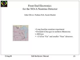
Front End Electronics for the NOvA Neutrino Detector John Oliver. Long baseline neutrino experiment Fermilab (Chicago) to northern Minnesota (~800 km) ~20-25 kTon “Far” and smaller “Near” detectors (Number given for 20 kTon in this document). Electronics & DAQ Organization.

E N D
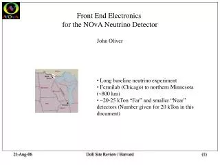
Front End Electronics for the NOvA Neutrino Detector John Oliver • Long baseline neutrino experiment • Fermilab (Chicago) to northern Minnesota (~800 km) • ~20-25 kTon “Far” and smaller “Near” detectors (Number given for 20 kTon in this document) DoE Site Review / Harvard
Electronics & DAQ Organization • L2 Manager – L. Mualem / U. Minn • Electronic Project Engineer – J. Oliver / Harvard • Front End Boards (FEBs) • L3 Manager – J.Oliver • Elect Eng – N. Felt • Technician / designer – S. Harder • Test software – J. Boehm • DAQ – FNAL • Power Distribution & Slow Controls – U. Va DoE Site Review / Harvard
NOvA Far Detector • ~ 500,000 channels of liquid scintillator / wavelength shifting fiber cells • Readout by 32 channel Avalanche Photo Diodes (10 pf per pixel ) • Gain ~ 100 @ -15C • MIP = ~ 25 photoelectrons @ far end of cell • 2,500 e / minimum ionizing signal • Neutrino interactions in 10 ms spill every ~ 2 sec • Signal dominated by cosmic rays ~ 400 Hz/pixel DoE Site Review / Harvard
Power Distribution Data Concentrator DAQ Heirarchy – 64 FEBs to one “Data Concentrator FEBs Beam Beam Beam DAQ DoE Site Review / Harvard
FEB DCM FEB DAQ & Timing GPS Receiver DCM FEB DCM DAQ Hierarchy • 250 Data Concentrator Modules connected to CPU Farm via ethernet switches & timing cables. • All pixel hit data sent through Concentrators to CPU farm – Timing signal take reverse path • Each “hit” 32 bit timestamp (62.5 ns / bin, synched to Global timing system) + pulseheight • Global timing system with GPS receiver to correlate timing with NUMI beam spills • All data are buffered for ~ 10 seconds • NUMI beamline spill is GPS timestamped & transmitted to Far Detector via internet (as is now done in MINOS) • In 10 sec buffer period, internet efficiency of spill signal is ~ 100% DoE Site Review / Harvard
Front End Board (FEB) Architecture APD Module DAQ ASIC ADC FPGA TE Cooler Control • Thermoelectric cooler maintains – 15C at APD • ASIC integrates & shapes 32 signal channels from APD • Selectable risetime & falltime constants • ASIC’s 8:1 Multiplexers run @ 16 MHz to sample each channel at 500 ns/sample • ASIC’s four outputs are continuously digitized by quad ADC @ 16 Msps and sent to FPGA • ~ 16,000 FEBs in NOvA Far Detector DoE Site Review / Harvard
Readout Electronics & Noise • APD noise • Minimum noise dominated by APD leakage of ~ 1 – 2 nA @ -15C • Dual Correlated Sampling would yield current (parallel) noise of ~100 e rms @ DT ~ 1 ms • Keep APDs cold! • Front end electronics & noise • Integrate signals in ASIC preamplifier with low noise • Dual Correlated Sampling with controlled risetime constant of a few hundred ns would yield ~ 150 e rms Readout objective is to minimize both noise components • Readout strategy • Sample & digitize each APD integrated signal continuously every 500 ns • Digitize all samples off-chip (low cost external ADCs) & send to FPGA • Perform multiple correlated sampling filters in local FPGA • Extract pulseheight & timestamp locally for each hit • Find “in spill” hits by timestamp in DAQ system (no trigger or spill signals on Front End Board) DoE Site Review / Harvard
Tf Tf Tf Tf 8 8 8 8 Tr Tr Tr Tr 8:1 Mux 8:1 Mux 8:1 Mux 8:1 Mux 32 ch ASIC (T. Zimmerman / FNAL) • 16 MHz multiplexers • 2 Msps per channel • Adjustable risetime & falltime • Status • Prototypes fabricated on TSMC 0.25u CMOS • Tested & work as per simulations DoE Site Review / Harvard
Sampled waveform g ( x ) g ( n ) 6 5 4 3 2 1 0 1 2 3 4 5 6 Signal Processing – Pulseheight & Timing • Use multiple correlated pairs of samples centered on leading edge • Weight the pairs by optimal coefficients • Optimal coefficients depend on noise spectrum • Parallel noise favors inner pair (small sampling time, small no of samples) • Series noise favors multiples pairs (long risetime constant, large number of samples) • Calibration • “Learn” noise spectrum by sampling baseline (~ 100us @ 2 - 16 Msps) • Compute optimal digital filter parameters offline • Download parameters back to FEBs DoE Site Review / Harvard
100 us Filter simulation & testing • DSP filter tests • Measurements from prototype electronics • Simulated noise pulses Advantage Can easily vary noise sources (leakage current, thermal noise) DoE Site Review / Harvard
DSP example – Timing extraction (N. Felt) • Matched filter Convolute signal with stored “ideal” pulse shape • Convolution yields sharply peaked function of time • Apply interpolation filter ~ 60ns timing resolution with ~ 500ns sampled signal (test data) DoE Site Review / Harvard
Summary • Flexible architecture : Continuous digitization + DSP • 2 MSPS DSO on every channel : Local analysis in FPGA • Algorithms optimized off-line for pulseheight & timing • In-situ diagnostics: Opens, shorts, APD high voltage, etc • NUMI beam spill signal not required “in-time” at FEBs • Spill signal sent to Far Detector via internet after spill • All in-spill data sorted for time-stamp and saved to disc • Low cost Front End Electronics • Recent production electronics experience at Harvard • ATLAS MDT Front End Electronics • 75k chips produced & tested • 16k Mezzanine cards produced*, tested, and delivered to ATLAS *We gratefully acknowledge Weizmann Institute for Mezz Card production in Israel DoE Site Review / Harvard