Radiosity for Point-Sampled Geometry
Radiosity for Point-Sampled Geometry. Yoshinori Dobashi. Tsuyoshi Yamamoto. ( Hokkaido University ). Tomoyuki Nishita. ( The University of Tokyo ). Overview. Introduction Background and Motivation Previous Work Radiosity Method Proposed Method Basic Idea

Radiosity for Point-Sampled Geometry
E N D
Presentation Transcript
Radiosity forPoint-Sampled Geometry Yoshinori Dobashi Tsuyoshi Yamamoto (Hokkaido University) Tomoyuki Nishita (The University of Tokyo)
Overview • Introduction • Background and Motivation • Previous Work • Radiosity Method • Proposed Method • Basic Idea • Computation of Effective Area • Construction of Hierarchy • Radiosity Calculation • Adaptive Addition of Surfels • Examples • Conclusions and Future Work
Overview • Introduction • Background and Motivation • Previous Work • Radiosity Method • Proposed Method • Basic Idea • Computation of Effective Area • Construction of Hierarchy • Radiosity Calculation • Adaptive Addition of Surfels • Examples • Conclusions and Future Work
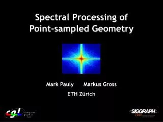
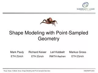
Object Polygons Points Background and Motivation • Point-sampled Geometry • Points sampled on surfaces of an object • No information on connectivity • Used for objects with complex shapes • Many researches on point-sampled geometry
Points as display primitive [Levoy85] • Point sample rendering [Grossman98] • Surfel [Pfister00], Q-splat [Rusinkiewica00] • Ray tracing [Shaufler00] • Surface splatting [Zwicker01] • Hardware-acceleration [Ren02] Background and Motivation • Previous methods for displaying point- sampled geometry • Points as display primitive [Levoy85] • Point sample rendering [Grossman98] • Surfel [Pfister00], Q-splat [Rusinkiewica00] • Ray tracing [Shaufler00] (Monte-Carlo approach) • Surface splatting [Zwicker01] • Hardware-acceleration [Ren02] • No method for radiosity (Finite element approach)
Background and Motivation • Goal of this research • Radiosity method for point-sampled geometry • Condition • Diffuse surfaces
Overview • Introduction • Background and Motivation • Previous Work • Radiosity Method • Proposed Method • Basic Idea • Computation of Effective Area • Construction of Hierarchy • Radiosity Calculation • Adaptive Addition of Surfels • Examples • Conclusions and Future Work
light Radiosity Method direct indirect
light n å = + r patch i B E F B i i j ij j = ¹ j 1 , j i qi q q cos cos 1 ò ò i j = F V dA dA ij ij i j Ai 2 A p r A A i rij j i ij qj Aj patch j Radiosity Method • Energy transfer between patches • A linear system Bi: radiosity Fij: form factor rj: diffuse reflectance Vij: visibility
light n å = + r patch i B E F B i i j ij j = ¹ j 1 , j i qi q q cos cos 1 ò ò i j = F V dA dA ij ij i j Ai 2 A p r A A i rij j i ij qj Aj patch j Radiosity Method • Energy transfer between patches • A linear system Bi: radiosity Fij: form factor rj: diffuse reflectance Vij: visibility
Radiosity Method • Energy transfer between patches light • A linear system n å = + r patch i B E F B i i j ij j = ¹ j 1 , j i qi q q cos cos i j = F A V ij ij j Ai 2 p r rij ij qj Bi: radiosity Fij: form factor rj: diffuse reflectance Vij: visibility Aj patch j
Overview • Introduction • Background and Motivation • Previous Work • Radiosity Method • Proposed Method • Computation of Effective Area • Construction of Hierarchy • Radiosity Calculation • Adaptive Addition of Surfels • Examples • Conclusions and Future Work
Use of surfels to represent object [Pfister00] normal ni point xi tangent disk max. distance between points in small neighborhood original surface Basic Idea Ri
Basic Idea 1. Computation of effective area 2. Construction of hierarchy 3. Computation of interreflection 4. Creation of final images
q q cos cos i j = F A ij j 2 p r ij Basic Idea 1. Computation of effective area • Form factor: (area) Area of tangent disk Effective area Considering overlap Overestimation due to overlap
Grouping neighbors Basic Idea 2. Construction of hierarchy • Large number of surfels • Increase in computation time • Efficient computation using hierarchy
Basic Idea 3. Computation of interreflection • Hierarchical radiosity with global refinement [Stamminger00] • Original points may not be sufficient • Adaptive addition of surfels 4. Creation of final images • Hardware accelerated surface splatting [Ren02]
Basic Idea 1. Computation of effective area 2. Construction of hierarchy 3. Computation of interreflection 4. Creation of final images
Basic Idea 1. Computation of effective area 2. Construction of hierarchy 3. Computation of interreflection 4. Creation of final images
Basic Idea 1. Computation of effective area 2. Construction of hierarchy 3. Computation of interreflection 4. Creation of final images
Use of exponential func. Effective Area Computation • Definition: effective area of surfel i DA: Differential area xi: Influence function • Condition of xi : ri y • Decreasing with distance DA(y)
Use of exponential func. Effective Area Computation • Definition: effective area of surfel i DA: Differential area xi: Influence function • Condition of xi : ri y • Decreasing with distance DA(y) • Taking into account overlap
DA + Total area: Sum of effective areas: Effective Area Computation • Simple case: Same normal vectors (coplanar disks) y = =
for cond. (1) for cond. (2) Effective Area Computation • Simple case: Same normal vectors (coplanar disks) (1) Decreasing with distance (exp func.) (2) Taking into account overlap • We use following influence function
DAj q disk i disk j rj ri DAi Effective Area Computation • General case • Effective area: • Problem: how to compute DA • Use of weighted average of DAi and DAj ( DAj = DAi/cosq )
Effective area for general case for details, see paper Effective Area Computation • General case • Effective area: • Problem: how to compute DA • Use of weighted average of DAi and DAj • Use of graphics hardware
m: number of neighboring surfels virtual camera virtual screen Effective Area Computation • Use of hardware-accelerated surface splatting [Ren02]
m: number of neighboring surfels Effective Area Computation • Use of hardware-accelerated surface splatting [Ren02] virtual camera R:w(r)DA additive blending a: w(r) virtual screen
m: number of neighboring surfels a R Effective Area Computation • Use of hardware-accelerated surface splatting [Ren02]
m: number of neighboring surfels DA a R Effective Area Computation • Use of hardware-accelerated surface splatting [Ren02] . . . . . ÷ =
Basic Idea 1. Computation of effective area 2. Construction of hierarchy 3. Computation of interreflection 4. Creation of final images
Computation of Interreflection • Hierarchical radiosity with global refinement [Stamminger00] • Algorithm 1. Compute intereflection 2. Evaluate errors 3. Replace surfels with their children 4. If error > z, go to step 1 (z : user-specified threshold) • Original points may not be sufficient • Addition of new surfels
shadow boundary Adaptive Addition of Surfels • Two conditions
shadow boundary Adaptive Addition of Surfels • Two conditions (1) Place surfels according to intensity gradient
shadow boundary Adaptive Addition of Surfels • Two conditions (1) Place surfels according to intensity gradient (2) Place surfels as uniformly as possible
- ( x x ) å j i = e d ij ij - x x j j i Adaptive Addition of Surfels • Local coordinate based on intensity gradient • Compute error vector
- ( x x ) å j i = e d w v ij ij - x x j j i u c:user-specified cnst. Ri:radius of surfel i Disk size: x0.5 Effective area: x0.25 Normal vetor, reflectance: interpolation Adaptive Addition of Surfels • Local coordinate based on intensity gradient • Compute error vector • Define local coordinate • Add four surfels at: (-cRi , cRi , 0.0), (-cRi , cRi , 0.0), (cRi , -cRi , 0.0), (-cRi , -cRi , 0.0)
Adaptive Addition of Surfels • Two conditions (1) Place surfels according to intensity gradient (2) Place surfels as uniformly as possible
Adaptive Addition of Surfels • Use of point repulsion method [Turk92][Pauly03] • Compute repulsive forces • Move surfels (Newly added surfels only)
Overview • Introduction • Background and Motivation • Previous Methods • Radiosity Method • Proposed Method • Basic Idea • Computing Representative Area • Construction of Hierarchy • Computing Interreflection using Progressive Radiosity • Adaptive addition of surfels • Examples • Conclusions and Future Work
3.5m x 3.5m, 400 surfels 0.8m 0.4m 0.2m 642 surfels Experimental Results • Three spheres in a simple room • Sum of effective areas: 8.23 m2 • True value: 8.04 m2 • Relative error: 2.63 % Very accurate
Experimental Results • Three spheres in a simple room Result Distribution of surfels (15,748 surfels) Computation time (radiosity): 38 sec. Computer: Pentium 4 (2.8GHz), GPU: nVidia Geforce4
Complex Results • Two bunnies in a simple room Result Distribution of surfels (72,068 surfels) Computation time (radiosity): 47 sec. Computer: Pentium 4 (2.8GHz), GPU: nVidia Geforce4
Complex Results • Gallery of statues Result Distribution of surfels (315,686 surfels) Computation time (radiosity): 2,541 sec. Computer: Pentium 4 (2.8GHz), GPU: nVidia Geforce4
Conclusions • Interreflection of light for point- sampled geometry • Efficient computation of effective areas • Adaptive addition of surfels Future Work • Specular reflection