CT Image Quality
CT Image Quality. Dr M A Oghabian Medical Physics Department, Tehran University of Medical Sciences. Sinogarm. Reconstruction Filters. CT number=1000×( m pixel- m water)/ m water. CT Number. Window width & window level. Quality criteria for CT images. Image Quality.


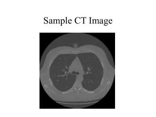
CT Image Quality
E N D
Presentation Transcript
CT Image Quality Dr M A Oghabian Medical Physics Department, Tehran University of Medical Sciences
CT number=1000×(mpixel-mwater)/mwater CT Number
Image Quality • 1) Spatial Resolution • 2) Density Resolution • 3) Noise • 4) Artifact • Partial volume effect • Beam Hardening • Star Artifact • Slice profile
Spatial Resolution (high contrast) Spatial Resolution is defined as: The number of line pairs per cm just visible in image
Spatial Resolution high contrast resolution • The minimum size of detail visualized in the image with a contrast >10%. It is affected by: • Reconstruction algorithm • Detector width • Slice thickness • Object to detector distance • X-ray tube focal spot size • Matrix size.
Spatial ResolutionLow contrast resolution • The size of detail that can be visualized when there is only a small difference in density • It limited by noise.
Slice Thickness and Pixel size • Thicker slice or bigger pixel size causes worse Spatial Resolution, but better SNR • Thicker Slice improve Density resolution • Higher mAs and more patient dose leads to better SNR
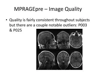
Noise Noise is obtained from the standard deviation in CT number in a region of interest (ROI) placed within the image
Noise • It affects the low contrast resolution • Noise dependents on the radiation dose • The medical problem is: to obtain an image with an acceptable level of noise while keeping the patient dose as low as reasonably achievable = Noise 1 dose
CT Number Accuracy • Measured CT number should be < ± 4 HU in the central ROI • CT number of water is by definition equal to 0 • CT number depends on tube voltage, filtration, object thickness
CT number uniformity • CT number of each pixel in the image of an homogeneous object should be the same over various regions • The difference in the CT number between a peripheral and a central region should be < 8HU • Differences are largely due to beam hardening phenomenon
CT number linearity • Linear relationship between the calculated CT number and the linear attenuation coefficient of each element of the object. Deviations from linearity should be < ± 5 HU
Z-Sensitivity (Imaged slice width) Plan view of a test object used to measure imaged slice widths for axial scans, to assess the accuracy of post patient collimation, and to calculate the geometric efficiency for the scanner
Alignment of indicating lights with scan, coronal and sagittal planes • Several methods can be used to perform these tests • The wrapped film is placed flat on the table and illuminated by the external scan plane light • The position of the light is marked on the film envelope and the table is moved automatically to the scan plane
Couch travel accuracy To assess the distance indicator accuracy, a ruler or tape measure placed alongside the table, to check that the degree of couch movement indicated on the gantry agrees with the actual distance moved.
Axial scan incrementation accuracy • Verification of incrementation accuracy between successive axial slices can be achieved by placing envelope-wrapped film on the couch (in the isocentre plane) and exposing it to an axial scan sequence • Narrow slices separated by a couch increment greater than 1 slice width can be used, and the distance between the lines on the film measured
Couch travel accuracy for helical scans • In helical scanning, to assess imaged distance accuracy, a Perspex test object containing two small radio-opaque markers, separated by a fixed distance (ex:20 cm) is used. • A helical run is planned to start at the first marker and to end at a distance x from the first marker • If couch travel is accurate during the helical scan, the markers should be clearly seen on the first and final images of the series.
Assessment of accuracy of gantry tilt • A film must be held vertically, so that it is parallel to the sagital plane • Three axial exposures with 0, max superior and max inferior gantry tilt are made using the same film: • The three scan planes should then be visible on the developed film
Dosimetry - CTDI in air (helical) Axial slice positions Helical scan (pitch 1) The Computed Tomography Dose Index (CTDI) in air can be measured using a 10cm pencil ionization chamber, bisected by the scan plane at the isocentre.
Dosimetry - CTDI in Perspex Phantoms Insert to plug holes Body phantom (or annulus to fit over haed phantom) Head phantom
( ) 1 1 2 = + CTDI CTDI CTDI n w 100, c 100, p C 3 3 Dosimetry - CTDI in Perspex Phantoms • Central and peripheral CTDI’s are used to calculate weighted CTDI, CTDIw: • CTDIws can be compared against diagnostic reference levels for standard scan examinations