Download
1 / 19
190 likes | 219 Vues
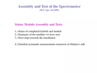
Assembly and Test of the Spectrometer (H.P. Apr. 16,1998). Status Module Assembly and Tests 1.) Status of completed hybrids and module 2.) Summary of the modules we have now 3.) Next steps towards the installation 4.) Detailed systematic measurements tomorrow in Markus’s talk.

E N D
Assembly and Test of the Spectrometer (H.P. Apr. 16,1998) Status Module Assembly and Tests 1.) Status of completed hybrids and module 2.) Summary of the modules we have now 3.) Next steps towards the installation 4.) Detailed systematic measurements tomorrow in Markus’s talk
Overview of Assembly and Test Test of - VA chips - flex cables - hybrids SMD/conn to hybrid Hybrid bonding Chip to hybrid backpl. contact Module gluing MS rework Module rework (fast) Module function test Module bonding Test of MS Sensor pool SURVEY measurement Module calibration Module SOURCE test Mounting on frames
Status of components • Hybrids • all hybrids assembled (a total of 1400 chips on 80 hybrids) • all hybrids tested and mounted to modules • lost only 3 of 80 hybrids -> extreme high yield of =96% • our “component drawers” are empty now • sensors: • all sensors for the first arm received (big congratulation to Willis & Gerrit) • all necessary sensors for the first arm are tested and mounted (few more T3’ for a spare module now at MIT) • Modules: • baseline: We are done with the module assembly and testing!!!
Status of components • Hybrids • all hybrids assembled (a total of 1400 chips on 80 hybrids) • all hybrids tested and mounted to modules • lost only 3 of 80 hybrids -> extreme high yield of =96% • our “component drawers” are empty now • sensors: • all sensors for the first arm received (big congratulation to Willis & Gerrit) • all necessary sensors for the first arm are tested and mounted (few more T3’ for a spare module now at MIT) • Modules: • baseline: We are done with the module assembly and testing!!!
Calibration test verify basic functionality determine the gain of the module find dead or substandard channels Acceptance criteria = less than 5% dead channels dead = gain less than 80% of normal gain noisy = noise larger than 3 times average noise Test with 90Srsource: verify sensor function verify signal measure signal/noise distribution Acceptance criteria = peak signal/noise > 10 A summary of Module Tests
Our Modules MOD2 (2 installed) Substandard ch. percentage/module peak S/N
Our Modules M7T2 (2 installed) Substandard ch. percentage/module peak S/N
Our Modules MOD6 (4 installed) Substandard ch. percentage/module peak S/N
Our Modules M4T4 (4 installed) Substandard ch. percentage/module peak S/N
Our Modules M5T4 (3 installed) Substandard ch. percentage/module peak S/N
Our Modules M7T3 (4 installed) Substandard ch. percentage/module peak S/N
Our Modules M5T5 (14 installed) Substandard ch. percentage/module peak S/N
Our Modules M4T5 (6 installed) Substandard ch. percentage/module peak S/N
A summary: The module peak signal-to-noise • All modules S/N better than 10 • Average S/N = 16:1
A summary: The number of defect channels(mainly pinholes, hardly broken lines or bonding shorts) % • All modules S/N better than 5% • Average number of substandard channels = 1%
A summary: The mounted sensors Iactive Vfd Rpoly - operation voltage below 90V (except 2 spare Mod1) - polysilicon resistor between 1-10MOhm - active area leakage current below 8uA typically 4-5uA
Conclusion • The module assembly and testing is FINISHED • The hybrids had an exceptional high yield • all modules significantly better than the specifications • Signal/Noise=16:1 • about 1% dead channels • The next fun- part: • survey and covers (in May/June) • mounting on frames (in July/August) • installation (in September) • What’s left to be said: A big thanks to the whole assembly group