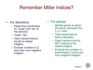
Remember Miller Indices?
For directions: Determine coordinates for “head” and “tail” of the direction “head”-”tail” Clear fraction/reduce results to lowest integers. Enclose numbers in [] and a bar over negative integers. For planes: Identify points at which the plane intercepts the x, y, z axis.

Remember Miller Indices?
E N D
Presentation Transcript
For directions: Determine coordinates for “head” and “tail” of the direction “head”-”tail” Clear fraction/reduce results to lowest integers. Enclose numbers in [] and a bar over negative integers. For planes: Identify points at which the plane intercepts the x, y, z axis. Take reciprocals of these intercepts. Clear fractions and do NOT reduce to the lowest integers. Enclose the numbers in parentheses () and a bar over negative integers. Remember Miller Indices?
Special note for directions… • For Miller Indices of directions: • Since directions are vectors, a direction and its negative are not identical! • [100] ≠ [100] Same line, opposite directions! • A direction and its multiple are identical! • [100] is the same direction as [200] (need to reduce!) • [111] is the same direction as [222], [333]! • Certain groups of directions are equivalent; they have their particular indices because of the way we construct the coordinates. • Family of directions: <111>=[111], [111],[111],[111],…
Special note for planes… • For Miller Indices of planes: • Planes and their negatives are identical (not the case for directions!) • E.g. (020) = (020) • Planes and their multiples are not identical (Again, different from directions!) We can show this by defining planar densities and planar packing fractions. • E.g. (010) ≠ (020) See example! • Each unit cell, equivalent planes have their particular indices because of the orientation of the coordinates. • Family of planes: {110} = (110),(110),(110),(101), (101),… • In cubic systems, a direction that has the same indices as a plane is perpendicular to that plane.
(c) 2003 Brooks/Cole Publishing / Thomson Learning™ Example: Calculating the Planar Density Calculate the planar density for the (010) and (020) planes in simple cubic polonium, which has a lattice parameter of 0.334 nm. a0 a0
(a0)2 SOLUTION The total atoms on each face is one. The planar density is: However, no atoms are centered on the (020) planes. Therefore, the planar density is zero. The (010) and (020) planes are not equivalent!
4 3 = a R 3 atoms 2 2D repeat unit 1 a 1 atoms atoms 12.1 = 1.2 x 1019 = = Planar Density = 2 nm2 m2 4 3 R 3 area 2D repeat unit Planar Density of (100) Iron 2D repeat unit Solution: At T < 912C iron has the BCC structure. (100) Radius of iron R = 0.1241 nm
2 æ ö 4 16 ç ÷ = = = = 2 2 2area 2 ah 3 3 3 3 a R R ç ÷ 3 3 atoms è ø 2D repeat unit 0.5 atoms Planar Density = atoms = = 7.0 0.70 x 10¹⁹ m2 nm2 16 3 2 R area 6 2D repeat unit Planar Density of (111) Iron There are only (3)(1/6)=1/2 atoms in the plane. h 3 = h a 2
In-Class Exercise 1: Determine planar density Determine the planar density for BCC lithium in the (100), (110), and the (111) planes. atomic radius for Li = 0.152 nm
Solution for plane (100) For (100):
Solution for plane (110) For (110): It is important to visualize how the plane is cutting across the unit cell – as shown in the diagram!
Solution for plane (111) For (111): Note: Since the (111) does NOT pass through the center of the atom in the middle of the BCC unit cell, we do not count it!
In-Class Exercise 2: Determine planar density Determine the planar density for FCC nickel in the (100), (110), and (111) planes. atomic radius for Nickel= 0.125 nm Remember when visualizing the plane, only count the atoms that the plane passes through the center of the atom. If the plane does NOT pass through the center of that atom, we do not count it!
a0 Solution for plane (100) For (100):
Solution for plane (110) For (110): It is important to visualize how the plane is cutting across the unit cell – as shown in the diagram! a0
Solution for plane (111) For (111): Again try to visualize the plane, count the number of atoms in the plane:
Home Exercise: Determine planar density Determine the planar density for (0001) plane for an HCP unit cell Titanium atomic radius for titanium is 0.145 nm
Crystals as Building Blocks • Some engineering applications require single crystals: --turbine blades(Co and Ni superalloys) --diamond single crystals for abrasives Fig. 8.33(c), Callister 7e. (Fig. 8.33(c) courtesy of Pratt and Whitney). (Courtesy Martin Deakins, GE Superabrasives, Worthington, OH. Used with permission.) • Properties of crystalline materials often related to crystal structure. --Ex: Quartz fractures more easily along some crystal planes than others.
Poly crystal Material Single crystal Grains
Polycrystals Anisotropic • Most engineering materials are polycrystals. Adapted from Fig. K, color inset pages of Callister 5e. (Fig. K is courtesy of Paul E. Danielson, Teledyne Wah Chang Albany) 1 mm Isotropic • Nb-Hf-W plate with an electron beam weld. • Each "grain" is a single crystal. • If grains are randomly oriented, overall component properties are not directional. • Grain sizes typ. range from 1 nm to 2 cm (i.e., from a few to millions of atomic layers).
Single vs Polycrystals E (diagonal) = 273 GPa E (edge) = 125 GPa • Single Crystals Data from Table 3.3, Callister 7e. (Source of data is R.W. Hertzberg, Deformation and Fracture Mechanics of Engineering Materials, 3rd ed., John Wiley and Sons, 1989.) -Properties vary with direction: anisotropic. -Example: the modulus of elasticity (E) in BCC iron: • Polycrystals 200 mm -Properties may/may not vary with direction. -If grains are randomly oriented: isotropic. (Epoly iron = 210 GPa) -If grains are textured, anisotropic. Adapted from Fig. 4.14(b), Callister 7e. (Fig. 4.14(b) is courtesy of L.C. Smith and C. Brady, the National Bureau of Standards, Washington, DC [now the National Institute of Standards and Technology, Gaithersburg, MD].)
iron system liquid 1538ºC -Fe BCC 1394ºC -Fe FCC 912ºC BCC -Fe Section 3.6 – Polymorphism • Two or more distinct crystal structures for the same material (allotropy/polymorphism) titanium , -Ti carbon diamond, graphite
Section 3.16 - X-Ray Diffraction • Diffraction gratings must have spacings comparable to the wavelength of diffracted radiation. • Can’t resolve spacings • Spacing is the distance between parallel planes of atoms.
(c) 2003 Brooks/Cole Publishing / Thomson Learning • Destructive (out of phase) x-ray beam gives a weak signal. • Reinforcing (in phase) interactions between x-rays and the crystalline material. Reinforcement occurs at angles that satisfy Bragg’s law.
detector “1” incoming reflections must X-rays “2” be in phase for “1” a detectable signal outgoing X-rays l extra “2” Adapted from Fig. 3.19, Callister 7e. distance q q travelled spacing by wave “2” d between planes X-ray nl intensity q d= c 2sin (from detector) q q c X-Rays to Determine Crystal Structure • Incoming X-rays diffract from crystal planes. Measurement of critical angle, qc, allows computation of planar spacing, d.
(c) 2003 Brooks/Cole Publishing / Thomson Learning • Diagram of a diffractometer, showing powder sample, incident and diffracted beams. • (b) The diffraction pattern obtained from a sample of gold powder.
z z z c c c y y y a a a b b b x x x X-Ray Diffraction Pattern (110) (211) Intensity (relative) (200) Diffraction angle 2q Diffraction pattern for polycrystalline a-iron (BCC) Adapted from Fig. 3.20, Callister 5e.
Bragg’s Law: Bragg’s Law: • Where is half the angle between the diffracted beam and the original beam direction • is the wavelength of X-ray d is the interplanar spacing Interplanar spacing: d Miller Indices
SUMMARY • Atoms may assemble into crystalline or amorphous structures. • Common metallic crystal structures are FCC, BCC, and HCP. Coordination number and atomic packing factor are the same for both FCC and HCP crystal structures. • We can predict the density of a material, provided we know the atomic weight, atomic radius, and crystal geometry (e.g., FCC, BCC, HCP). • Crystallographic points, directions and planes are specified in terms of indexing schemes. Crystallographic directions and planes are related to atomic linear densities and planar densities.
SUMMARY • Materials can be single crystals or polycrystalline. Material properties generally vary with single crystal orientation (i.e., they are anisotropic), but are generally non-directional (i.e., they are isotropic) in polycrystals with randomly oriented grains. • Some materials can have more than one crystal structure. This is referred to as polymorphism (or allotropy). • X-ray diffraction is used for crystal structure and interplanar spacing determinations.