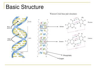
Understanding the Basic Structure of Computers
Explore the fundamental components and operations of computers, from machine instructions to system software and performance issues. Learn about input/output units, processors, memory, and control units. Delve into the history and development of computers.

Understanding the Basic Structure of Computers
E N D
Presentation Transcript
Chapter 1 Basic Structure of Computers • Basic structure of a computer • Intro to Machine instructions and their execution • Intro to system software that enables the preparation and execution of programs • Intro to performance issues in computer systems • The history of computer development Lecture
Computer Hardware Electronic circuits Displays Magnet and optical storage media Electromechanical equipment Communication facilities Computer Architecture Instruction set specifications Hardware used to implement the instructions In understand the basic structure of computers, one must understand Programming and Software components in a computer system Lecture
In general, how a computer operates • Computer accepts info in the form of programs and data via an input unit and stores the data in memory • The information stored in memory is fetched, under program control, into an ALU, where it is processed • The processed info leaves the computer via an output unit • All activities inside the computer are directed by the control unit Lecture
Basic Structure of Computers Coded info is stored in memory for later use Program is stored in memory and determines the processing steps Input unit accepts code info from human operators, electromechanical devices (ie keyboard), other computers via networks ALU uses the coded info to perform the desired operations All actions are coordinated by the control unit The output unit sends the results back out externally Collectively called the I/O unit Collectively called the processor Lecture
Instructions or Machine Instructions Governs the transfer of info within a computer Governs the transfer of info between the computer and its I/O devices Specifies the arithmetic and logic operations to be performed List of instructions perform tasks that are called programs Programs stored in memory Computer controlled by the program except for external interrupts by an operator or I/O device Data Numbers and encoded characters used as operands by the instructions Typically means digital information If a program is to be processed by another program, it could be considered “data” (high-level language is data to a compiler that compiles to machine language) Each number, character or instruction is encoded as a string binary digits called bits Binary-coded Decimal (BCD) is an encoding scheme using only 4 bits – ASCII uses 7 bits – EBCDIC uses 8 bits Info handled by a computer Lecture
Input Unit • Coded information is accepted through input devices • Examples • Keyboard – key corresponds to letter, key press translate letter to binary code – code either stored in memory or used by processor • Joysticks • Trackballs • Mouses • Microphone – captures audio via sampling and converted to codes (recall “pulse code modulation (PCM) in networking) Lecture
Memory Unit • Stores the programs and coded information • Two classes of storage • Primary Storage • Considered the “Fast memory” • Program is stored in primary storage when being executed • Memory organized by words containing bits versus individual cells - words that can be stored or retrieved in one operation • Word lengths can range 16 to 64 bits • Uses addresses to access the words • Memory is structured in hierarchy (or levels) – small and fast memory tightly coupled with processor are caches – largest and slowest memory is called main memory • Secondary Storage • Cheaper than primary memory • Is used when large amounts of data and many programs have to be stored • Catered for info accessed infrequently • ie. magnetic disks and tapes and optical disks (CD-ROMs) Lecture
Arithmetic and Logic Unit • Executes most computer operations • For example • Adding two numbers in memory – the numbers are brought into the “processor” and the actual addition is performed by the “ALU” – the sum may to stored in memory or retained in the processor • The operands are stored in high-speed storage elements called registers - each register can store one word of data • Access time to registers is faster than access time to cache • The ALU and control units are many time faster than other computer devices – therefore, a processor can control a number of external devices all at the same time Lecture
Output Unit • Sends processed results to the outside of the system • For example • Printer • Graphic displays Lecture
Control Unit • Coordinates the memory, ALU and I/O units in • processing info and • in performing input and output operations • Sends control signals to the various units • Senses the states of the various units • The program instructions control the I/O transfers HOWEVER, the actual timing signals that governs the transfers are generated by the control unit • Actually “control circuitry” is not a single unit but rather distributed throughout the computer Lecture
Basic Operational Concepts Typical Instruction Add LOCA, R0 To the operand in a register R0 in the processor Adds the operand at memory location LOCA Operand at LOCA is preserved however, the operand in register R0 is overwritten The sum is placed in a register R0 in the processor ADD instruction combines a memory access operation with an ALU operation Transfer content from memory location LOCA into processor register R1 Load LOCA, R1 Add R1,R0 Adds the content of registers R1 and R0 and places the sum into R0 Lecture
Basic Operational Concepts The memory address register (MAR) and memory data register (MDR) facilitates communication with memory. The transfer between the memory and the processor starts by sending the address of the memory location to the memory unit and issuing appropriate control signals The MAR holds the address of the location to be accessed The processor also contains numerous registers used for different purposes The MDR contains the data to be written into or read out of the address location. The program counter (PC) is a register that keeps track of the execution of a program – it contains the address of the next instruction to be fetch and executed The instruction register (IR) holds the instruction that is currently being executed – its output to the control unit so the CU can generate the timing signals involved in executing the instruction General purpose registers Lecture
Basic Operational Concepts • Program is loaded to memory via the input unit • Execution of the program starts when the program counter (PC) points to the first instruction • Contents of the PC is sent to the memory address register (MAR) and a read control signal is sent to memory • After memory access time finishes, the 1st instruction is read out of memory and loaded into the memory data register (MDR) • Contents of the MDR are transferred to the instruction register (IR) • Now the instruction is ready to be decoded and executed • Provided the instruction requires an operation that warrants the ALU, the operand is fetch from memory by sending the operand’s address to the MAR and starting a Read cycle • Then operand is transferred from memory to the MDR • Then transferred from the MDR to the ALU • After all the operands are fetched – the ALU performs its operation • Result is stored in memory, then set to the MDR • The address of where the result will be stored in memory is sent to the MAR and a Write cycle is started • The PC is incremented to point to the next instruction • NOTE: normal operations can be preempted by I/O interrupts • In this case, the internal state of the PC, general registers and control info are stored in memory • After the interrupt-service routine is completed, state of the processor is restored Lecture
Bus Structures We haven’t discussed how these units are connected The units must organized and connected so that ALL units can handle one FULL WORD at a given time – when a WORD is transferred between units, the word is transferred in parallel The group of lines, one bit per line, is called a BUS BUS carries data, addresses and control info Buffer registers are used to hold the info during transfers – once the info makes it to the buffer, the buss and process can be released Single bus does one transfer at a time – only 2 units can actively use the bus at a given time Lecture
Software System software is a collection of programs that are executed as needed to perform various functions such as: • Receiving and interpreting user commands • Entering and editing application programs • Managing the storage and retrieval of files on secondary storage devices • Running applications like word processors, spreadsheets and etc • Controlling I/O units • Translating programs to machine instructions • Linking programs with library routines • Application programs written in high-level language (Java, C++) • High-level language independent of particular computer • Compiler used to translate high-level language to machine language program Lecture
Software – Operating System Operating System (OS) is a collection of routines used to control the sharing of and interaction among various computer units as they execute application programs • Assign computer resources to individual application programs • Assign memory and magnetic disk space to program • Move data between memory and disk units • Handle I/O operations OS loads application program from disk OS loads data file from disk Transfer data file from disk and prints the results Waits for transfer to occur, then passes execution control to application program Waits for transfer to occur, then passes execution control to application program Lecture
Performance • Performance is a measure of how fast a computer can execute a program • Performance is affected by: • Design of the computer’s hardware • Machine language instruction set • Compiler • The overall time for the program to execute is the “elapsed time” • The times with in the elapsed time the processor is active is called the “processor time” • To increase “performance” is to minimized needed “processor time” • Elapse time depends on all of the units – the processor time depends on the hardware involved in the execution of the machine instructions Lecture
Performance • As mentioned, the processor time depends on the hardware involved in the execution of the machine instructions • Processor • Memory • Bus connecting processor and memory In helping with performance, the cache memory and processor can be fabricated on the same chip • In helping with performance, as instructions are fetched, a copy is placed in cache • Later, if the same instruction or data item is needed, it is read directly from cache Lecture
Processor Clock • Processor circuits are controlled by a timing signal called a “clock” • Clock defines the regular time intervals called “clock cycles” • The various “steps” that make up an “instruction” can be completed in a clock cycle • The length of one clock cycle is P, the clock rate is the inverse, R=1/P • R=1/P is measured in cycles per second • Modern Personal Computers have clock rates ranging from few million to over a billion cycles per second (or hertz) – recall data comm: • Mega hertz (MHz, million) • Giga hertz (GHz, billion) • Example: 1.25 GHz corresponds to a clock period of 1/1.25 = 0.8 nanoseconds • The basic performance equation, T = (NxS)/R, is the program execution time • Where N = # instructions, S = avg # of steps per instruction, R = clock rate in cycles per second • To make program execution time, T, better • Seek ways to reduce N and S • Seek ways to increase R Lecture
Pipelining and Superscalar Operation • Can improve performance by overlapping the execution of successive instructions, using a technique called “pipelining” • A higher degree of concurrency can be achieved if there were multiple pipelines implemented in the processor – called superscalar execution Clock Rate • Can increase the clock rate • Improving the integrated circuit (IC) and making the circuits faster, thus reducing the time to complete a basic step • Reduce the amount of processing in a basic step Lecture
Instruction Set: CISC and RISC • Simple instructions have a small number of steps per instruction (small S) • Complex instructions have a larger number of steps per instruction (larger S) • Therefore, a processor using only simple instructions, could have • a large number of instructions, N, and a small # steps per instruction, S • Therefore, a processor using only complex instructions, could have • a small number of instructions, N, and a large # steps per instruction, S • It is NOT obvious which one is best • Although complex instructions are less in number and therefore with pipelining, one can better achieve a lower S value • Simple instructions achieve more efficient pipelining • Processors that use simple instructions are called Reduced Instruction Set Computers (RISC) (pronounced “Risk”) • Processors that use complex instructions are called Complex Instruction Set Computers (CISC) (pronounced “Sisk”) Lecture
Performance Measurement • It is very difficult to use execution time, T, as a measure of performance of a computer • Benchmark programs are used to measure computer performance • Organization called System Performance Evaluation Corp (SPEC) selects and publishes application programs for different application domains • A reference computer is used • The SPEC rating is (reference computer runtime)/(test computer runtime) • If SPEC=50, means test computer is 50 times faster than reference computer • Test is repeated for all programs in the test suite and an geometric average represents an overall SPEC rating Lecture
History Read section 1.8 for more details • 1st Generation: John von Neumann, vacuum tube technology, magnetic memory and storage • 2nd Generation: AT&T Bell labs (1940s) developed the “Transistor” to replace the vacuum tube – compilers invented • 3rd Generation: fabrication of transistors on silicon chip – microprogramming, parallelism and pipelining – cache and virtual memory • 4th Generation: complete processors and large sections of main memory were all on a single chip – Very Large Scale Integration (VLSI) tens of thousands transistors on a chip Lecture