Download
1 / 77
820 likes | 891 Vues
Learn the basic structure of computers, including functional units, memory operations, and how data is processed within a computer system. Understand the role of arithmetic and logic units, input/output units, control units, and memory in computer operations.

E N D
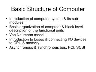
What is a computer? • Simply put, a computer is a sophisticated electronic calculating machine that: • Accepts input information, • Processes the information according to a list of internally stored instructions and • Produces the resulting output information. • Functions performed by a computer are: • Accepting information to be processed as input. • Storing a list of instructions to process the information. • Processing the information according to the list of instructions. • Providing the results of the processing as output. • What are the functional units of a computer?
Functional units of a computer Arithmetic and logic unit(ALU): • Performs the desired operations on the input information as determined by instructions in the memory Input unit accepts information: • Human operators, • Electromechanical devices • Other computers Memory Arithmetic & Logic Input Instr1 Instr2 Instr3 Data1 Data2 Output Control Processor I/O Stores information: • Instructions, • Data Control unit coordinates various actions • Input, • Output • Processing Output unit sends results of processing: • To a monitor display, • To a printer
Information in a computer -- Instructions • Instructions specify commands to: • Transfer information within a computer (e.g., from memory to ALU) • Transfer of information between the computer and I/O devices (e.g., from keyboard to computer, or computer to printer) • Perform arithmetic and logic operations (e.g., Add two numbers, Perform a logical AND). • A sequence of instructions to perform a task is called a program, which is stored in the memory. • Processor fetches instructions that make up a program from the memory and performs the operations stated in those instructions. • What do the instructions operate upon?
Information in a computer -- Data • Data are the “operands” upon which instructions operate. • Data could be: • Numbers, • Encoded characters. • Data, in a broad sense means any digital information. • Computers use data that is encoded as a string of binary digits called bits.
Real world Input unit Binary information must be presented to a computer in a specific format. This task is performed by the input unit: - Interfaces with input devices. - Accepts binary information from the input devices. - Presents this binary information in a format expected by the computer. - Transfers this information to the memory or processor. Computer Memory Input Unit Keyboard Audio input …… Processor
Memory unit • Memory unit stores instructions and data. • Recall, data is represented as a series of bits. • To store data, memory unit thus stores bits. • Processor reads instructions and reads/writes data from/to the memory during the execution of a program. • In theory, instructions and data could be fetched one bit at a time. • In practice, a group of bits is fetched at a time. • Group of bits stored or retrieved at a time is termed as “word” • Number of bits in a word is termed as the “word length” of a computer. • In order to read/write to and from memory, a processor should know where to look: • “Address” is associated with each word location.
Memory unit (contd..) • Processor reads/writes to/from memory based on the memory address: • Access any word location in a short and fixed amount of time based on the address. • Random Access Memory (RAM) provides fixed access timeindependent of the location of the word. • Access time is known as “Memory Access Time”. • Memory and processor have to “communicate” with each other in order to read/write information. • In order to reduce “communication time”, a small amount of RAM (known as Cache) is tightly coupled with the processor. • Modern computers have three to four levels of RAM units with different speeds and sizes: • Fastest, smallest known as Cache • Slowest, largest known as Main memory.
Memory unit (contd..) • Primary storage of the computer consists of RAM units. • Fastest, smallest unit is Cache. • Slowest, largest unit is Main Memory. • Primary storage is insufficient to store large amounts of data and programs. • Primary storage can be added, but it is expensive. • Store large amounts of data on secondary storage devices: • Magnetic disks and tapes, • Optical disks (CD-ROMS). • Access to the data stored in secondary storage is slower, but takes advantage of the fact that some information may be accessed infrequently. • Cost of a memory unit depends on its access time, lesser access time implies higher cost.
Arithmetic and logic unit (ALU) • Operations are executed in the Arithmetic and Logic Unit (ALU). • Arithmetic operations such as addition, subtraction. • Logic operations such as comparison of numbers. • In order to execute an instruction, operands need to be brought into the ALU from the memory. • Operands are stored in general purpose registers available in the ALU. • Access times of general purpose registers are faster than the cache. • Results of the operations are stored back in the memory or retained in the processor for immediate use.
Real world Output unit • Computers represent information in a specific binary form. Output units: - Interface with output devices. - Accept processed results provided by the computer in specific binary form. - Convert the information in binary form to a form understood by an output device. Computer Memory Printer Graphics display Speakers …… Output Unit Processor
Control unit • Operation of a computer can be summarized as: • Accepts information from the input units (Input unit). • Stores the information (Memory). • Processes the information (ALU). • Provides processed results through the output units (Output unit). • Operations of Input unit, Memory, ALU and Output unit are coordinated by Control unit. • Instructions control “what” operations take place (e.g. data transfer, processing). • Control unit generates timing signals which determines “when” a particular operation takes place.
Execution of an instruction • Recall the steps involved in the execution of an instruction by a processor: • Fetch an instruction from the memory. • Fetch the operands. • Execute the instruction. • Store the results. • Several issues: • Where is the address of the memory location from which the present instruction is to be fetched? • Where is the present instruction stored while it is executed? • Where and what is the address of the memory location from which the data is fetched? • ...... • Basic processor architecture has several registers to assist in the execution of the instructions.
Basic processor architecture(Fig A) Address of the memory location to be accessed Memory Address of the next instruction to be fetched and executed. Data to be read into or read out of the current location MAR MDR Control R0 PC General purpose registers R1 IR ALU Instruction that is currently being executed R(n-1) - n general purpose registers Processor 13
How are the functional units connected? • For a computer to achieve its operation, the functional units need to communicate with each other. • In order to communicate, they need to be connected. Input Output Memory Processor Bus • Functional units may be connected by a group of parallel wires. • The group of parallel wires is called a bus. • Each wire in a bus can transfer one bit of information. • The number of parallel wires in a bus is equal to the word length of a computer
Basic processor architecture (contd..) Data Path Control Path MAR MDR Processor Control path is responsible for: • Instruction fetch and execution sequencing • Operand fetch • Saving results Data path: • Contains general purpose registers • Contains ALU • Executes instructions Memory 15
Registers in the control path • Instruction Register (IR): • Instruction that is currently being executed. • Program Counter (PC): • Address of the next instruction to be fetched and executed. • Memory Address Register (MAR): • Address of the memory location to be accessed. • Memory Data Register (MDR): • Data to be read into or read out of the current memory location, whose address is in the Memory Address Register (MAR).
Fetch/Execute cycle • Execution of an instruction takes place in two phases: • Instruction fetch. • Instruction execute. • Instruction fetch: • Fetch the instruction from the memory location whose address is in the Program Counter (PC). • Place the instruction in the Instruction Register (IR). • Instruction execute: • Instruction in the IR is examined (decoded) to determine which operation is to be performed. • Fetch the operands from the memory or registers. • Execute the operation. • Store the results in the destination location. • Basic fetch/execute cycle repeats indefinitely.
Memory organization • Recall: • Information is stored in the memory as a collection of bits. • Collection of bits are stored or retrieved simultaneously is called a word. • Number of bits in a word is called word length. • Word length can be 16 to 64 bits. • Another collection which is more basic than a word: • Collection of 8 bits known as a “byte” • Bytes are grouped into words, word length can also be expressed as a number of bytes instead of the number of bits: • Word length of 16 bits, is equivalent to word length of 2 bytes. • Words may be 2 bytes (older architectures), 4 bytes (current architectures), or 8+ bytes (modern architectures).
Memory organization (contd..) • Accessing the memory to obtain information requires specifying the “address” of the memory location. • Recall that a memory has a sequenceof bits: • Assigning addresses to each bit is impractical and unnecessary. • Typically, addresses are assigned to a single byte. • “Byte addressable memory” • Suppose k bits are used to hold the address of a memory location: Size of the memory in bytes is given by: 2k where k is the number of bits used to hold a memory address. E.g., for a 16-bit address, size of the memory is 216= 65536 bytes What is the size of the memory for a 24-bit address?
Memory organization (contd..) Byte 0 • Memory is viewed as a sequence of bytes. • Address of the first byte is 0 • Address of the last byte is 2k - 1, where k is the number of bits used to hold memory address • E.g. when k = 16, Address of the first byte is 0 Address of the last byte is 65535 • E.g. when k = 2, Address of the first byte is ? Address of the last byte is ? Byte 2k-1 20
Memory organization (contd..) Byte 0 Word #0 Byte 1 Consider a memory organization: 16-bit memory addresses Size of the memory is ? Word length is 4 bytes Number of words =Memory size(bytes) = ? Word length(bytes) Word #0 starts at Byte #0. Word #1 starts at Byte #4. Last word (Word #?) starts at Byte#? Byte 2 Byte 3 Byte 4 Word #1 Word #? Byte 65532 Byte 65533 Byte 65534 Byte 65535 21
Memory organization (contd..) Byte 0 Word #0 Byte 1 Byte 2 MAR Byte 3 Byte 4 MDR Word #1 MAR register contains the address of the memory location addressed Addr 65532 Byte 65532 Word #16383 Byte 65533 MDR contains either the data to be written to that address or read from that address. Byte 65534 Byte 65535 22
Byte Addressability • Byte addressable memory • Memory is organized in 16-bit words. • Two consecutive 16-bit words constitute one 32-bit long word. • Word address must be an even number, that is, words must be aligned on an even boundary. • Byte in the high-order position has the same address as the word, the byte in the low-order position has the next higher address. This is the big endian address assignment.
Big Endian Big Endian : (e.g., in IBM, Motorolla, Sun, HP) • lower byte addresses are used for the most significant bytes of the word • high order byte stored at lowest address • byte3 byte2 byte1 byte0 • Programmers/protocols should be careful when transferring binary data between Big Endian and Little Endian machines Eg: 46,78,96,54 (32 bit data) H BYTE <---------------- L BYTE 8000 46 8001 78 • 96 • 54
Little-Endian Assignment • Little Endian (e.g., in DEC, Intel) • » low order byte stored at lowest address • » byte0 byte1 byte2 byte3 • Eg: 46,78,96,54 (32 bit data) • H BYTE <---------------- L BYTE • 8000 54 • 8001 96 • 78 • 46
In case of 16 bit data, aligned words begin at byte addresses of 0,2,4,…………………………. In case of 32 bit data, aligned words begin at byte address of 0,4,8,…………………………. In case of 64 bit data, aligned words begin at byte addresses of 0,8,16,……………………….. In some cases words can start at an arbitrary byte address also then, we say that word locations are unaligned
Memory operations • Memory read or load: • Place address of the memory location to be read from into MAR. • Issue a Memory_read command to the memory. • Data read from the memory is placed into MDR automatically (by control logic). • Memory write or store: • Place address of the memory location to be written to into MAR. • Place data to be written into MDR. • Issue Memory_write command to the memory. • Data in MDR is written to the memory automatically (by control logic).
Instruction types • Computer instructions must be capable of performing 4 types of operations. • Data transfer/movement between memory and processor registers. • E.g., memory read, memory write • Arithmetic and logic operations: • E.g., addition, subtraction, comparison between two numbers. • Program sequencing and flow of control: • Branch instructions • Input/output transfers to transfer data to and from the real world.
Instruction types (contd..) • Examples of different types of instructions in assembly language notation. • Data transfers between processor and memory. • Move A, B (B = A). • Move A, R1 (R1 = A). • Arithmetic and logic operation: • Add A, B, C(C = A + B) • Sequencing: • Jump Label(Jump to the subroutine which starts at Label). • Input/output data transfer: • Input PORT, R5 (Read from i/o port “PORT” to register R5).
Specifying operands in instructions • Operands are the entities operated upon by the instructions. • Recall that operands may have to be fetched from a memory location to execute an operation. • Memory locations have addresses using which they can be accessed. • Operands may also be stored in the general purpose registers. • Intermediate value of some computation which will be required immediately for subsequent computations. • Registers also have addresses. • Specifying the operands on which the instruction is to operate involves specifying the addresses of the operands. • Address can be of a memory location or a register.
Source and destination operands • Operation may be specified as: • Operation source1, source2, destination • An operand is called a source operand if: • It appears on the right-hand side of an expression • E.g., Add A, B, C(C = A+ B) • A and B are source operands. • An operand is called a destination operand if: • It appears on the left-hand side of an expression. • E.g., Add A, B, C (C = A + B) • C is a destination operand.
Source and destination operands (contd..) • In case of some instructions, the same operand serves as both the source and the destination. • Same operand appears on the right and left side of an expression. • E.g. Add A, B (B = A + B) • B is both the source and the destination operand. • Another classification of instructions is based on the number of operand addresses in the instruction.
Instruction types • Instructions can also be classified based on the number of operand addresses they include. • 3, 2, 1, 0 operand addresses. • 3-address instructions are almost always instructions that implement binary operations. • E.g. Add A, B, C(C = A + B) • k bits are used to specify the address of a memory location, then 3-address instructions need 3*k bits to specify the operand addresses. • 3-address instructions, where operand addresses are memory locations are too big to fit in one word.
Instruction types (contd..) • 2-address instructions one operand serves as a source and destination: • E.g.Add A, B (B = A + B) • 2-address instructions need 2*k bits to specify an instruction. • This may also be too big to fit into a word. • 2-address instructions, where at least one operand is a processor register: • E.g.Add A, R1 (R1 = A + R1) • 1-address instructions require only one operand. • E.g. Clear A (A = 0) • 0-address instructions do not operate on operands. • E.g.Halt (Halt the computer) • How are addresses of operands specified in the instructions?
Problems(Q1.1 in Text book) • 1. List the steps needed to execute the machine instruction Add LOCA, R0 in terms of transfer between the components shown in Fig A • Transfer the contents of register PC to register MAR • Issue a Read command to memory, and then wait until it has • transferred the requested word into register MDR • Transfer the instruction from MDR into IR and decode it • Transfer the address LOCA from IR to MAR • Issue a Read command and wait until MDR is loaded • Transfer contents of MDR to the ALU • Transfer contents of R0 to the ALU • Perform addition of the two operands in the ALU and transfer result into R0 • Transfer contents of PC to ALU • Add 1 to operand in ALU and transfer incremented address to PC
Repeat the above problem for the machine instruction Add R1, R2, R3: Problems(Q1.2 in Text book) • Transfer the contents of register PC to register MAR • Issue a Read command to memory, and then wait until it has transferred the requested word into register MDR • Transfer the instruction from MDR into IR and decode it • Transfer contents of R1 and R2 to the ALU • Perform Addition of two operands in the ALU and transfer result into R3 • Transfer contents of PC to ALU • Add 1 to operand in ALU and transfer incremented address to PC
List the steps needed to execute the machine instruction Add LOCA, LOCB • Transfer the contents of register PC to register MAR • Issue a Read command to memory, and then wait until it has transferred the requested word into register MDR • Transfer the instruction from MDR into IR and decode it • Transfer the address LOCA from IR to MAR • Issue a Read command and wait until MDR is loaded • Transfer contents of MDR to the ALU • Transfer the address LOCB from IR to MAR • Issue a Read command and wait until MDR is loaded • Transfer contents of MDR to the ALU • Perform addition of the two operands in the ALU and transfer result into LOCB • Transfer contents of PC to ALU • Add 1 to operand in ALU and transfer incremented address to PC
Problems(Q1.3 in Text book) • Give a short sequence of machine instructions for the task: “Add the contents of memory location A to those of location B and place the answer in location C”. • Only Load LOC, Ri and Store Ri, LOC are available • Suppose that Move and Add instructions are available with the format • Move/Add Location1, Location2, is it possible to use fewer instructions to accomplish the task in Part a? If yes, give the sequence • Solution: • (a) • Load A,R0 • Load B,R1 • Add R0,R1 • Store R1,C • (b) Yes; • Move B,C • Add A,C
Performance • The speed with which a computer executes programs is affected bythe design of its hardware and its machine language instructions. • Because programs are usually written in a high-level language, performance is also affected by the compiler that translates programs into machine language. • For best performance, it is necessary to design the compiler, the machine instruction set and the hardware in a coordinated way. • Just as the elapsed time for the execution of a program depends on all units in a computer system, the processor time depends on the hardware involved in the execution of individual machine instructions. • This hardware comprises the processor and the memory, which are usually connected by a bus as shown in Fig.
Organization of cache and main memory Main Cache Processor memory memory Bus Why is the access time of the cache memory lesser than the access time of the main memory?
Processor Clock • Processor circuits are controlled by a timing signal called a clock. • The clock defines regular time intervals, called clock cycles. • To execute a machine instruction, the processor divides the action to be performed into a sequence of basic steps, such that each step can be completed in one clock cycle. • The length P of one clock cycle is an important parameter that affects processor performance. • Its inverse is the clock rate, R = 1/P, which is measured in cycles per second.
Basic Performance Equation • Let T be the processor time required to execute a program that has been prepared in some high-level language. • The compiler generates a machine language object program that corresponds to the source program. • Assume that complete execution of the program requires the execution of N machine language instructions. • The number N is the actual number of instruction executions and is not necessarily equal to the number of machine instructions in the object program. • Suppose that the average number of basic steps needed to execute • one machine instruction is S, where each basic step is completed in • one clock cycle. • If the clock rate is R cycles per second, the program execution time • is given by • This is referred to as the basic performance equation
Performance Measurement • Computer performance can be measured using benchmark programs. • To make comparisons possible, standardized programs must be used. • The performance measure is the time it takes a computer to execute a given benchmark. • A nonprofit organization called System Performance Evaluation Corporation (SPEC) selects and publishes representative application programs for different application domains, together with test results for many commercially available computers. • The selected program is compiled for the computer under test and the running time on a real computer is measured. • The same program is also compiled and run on one computer selected as a reference. The SPEC rating is computed as follows:
The test is repeated for all the programs in the SPEC suite, and the geometric mean of the results is computed. Let be the rating for program I in the suite. The overall SPEC rating for the computer is given by Where n is the number of programs in the suite.
Instruction Set :RISC and CISC • RISC (Reduced Instruction Set Computer) Architectures – Memory accesses are restricted to load and store instruction, and data manipulation instructions are register to register. – Addressing modes are limited in number. – Instruction formats are all of the same length. – Instructions perform elementary operations • CISC (Complex Instruction Set Computer) Architectures – Memory access is directly available to most types of instruction. – Addressing mode are substantial in number. – Instruction formats are of different lengths. – Instructions perform both elementary and complex operations.
Instruction Set Architecture • RISC (Reduced Instruction Set Computer) Architectures – Large register file – Control unit: simple and hardwired – pipelining • CISC (Complex Instruction Set Computer) Architectures – Register file: smaller than in a RISC – Control unit: often micro‐programmed – Current trend • CISC operation a sequence of RISC‐like operations
CISC Examples • Examples of CISC processors are the – System/360(excluding the 'scientific' Model 44), – VAX, – PDP‐11, – Motorola 68000 family – Intel x86 architecture based processors.
RISC Examples • Apple iPods (custom ARM7TDMI SoC) • Apple iPhone (Samsung ARM1176JZF) • Palm and PocketPC PDAs and smartphones (IntelXScale family, Samsung SC32442 ‐ ARM9) • Nintendo Game Boy Advance (ARM7) • Nintendo DS (ARM7, ARM9) • Sony Network Walkman (Sony in‐house ARM based chip) • Some Nokia and Sony Ericsson mobile phones