Download
1 / 9
90 likes | 116 Vues
Implementing advanced digital synthesis and phase jumping techniques in the Debuncher RF system to improve energy matching and beam stacking capabilities, as demonstrated in recent tests. Explore additional diagnostics and tuning strategies for optimal performance.

E N D
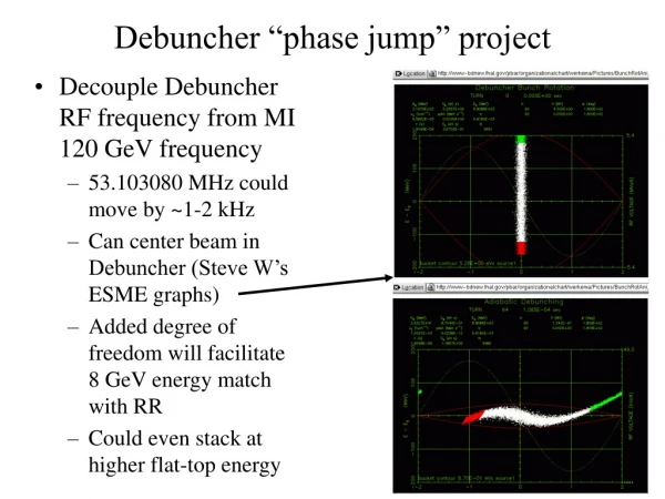
Decouple Debuncher RF frequency from MI 120 GeV frequency 53.103080 MHz could move by ~1-2 kHz Can center beam in Debuncher (Steve W’s ESME graphs) Added degree of freedom will facilitate 8 GeV energy match with RR Could even stack at higher flat-top energy Debuncher “phase jump” project
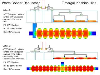
MI RF at 120 GeV (say 53.103 MHz): Desired Debuncher RF (say 53.101 MHz): digitally synthesized with DAC driven by programmable logic On MIBS $79 event, jump phase of synthesized Debuncher RF to match measured phase of MI RF, plus programmable offset phase jump bucket-to-bucket transfer still works
Implementation: reprogram spare MI damper board DAC output (x4) 12 bit, 424 MS/s Ethernet (Acnet etc) • Fast ADC + digital logic measures MI phase • Digital logic + fast DAC replaces VCO in Debuncher LLRF CPU slow control FPGA signal processing ADC input (x4) 12 bit, 212 MS/s TTL I/O
The FPGA (programmable logic) coding looks like something in between writing a program and drawing a schematic.
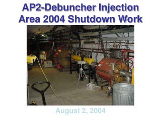
Debuncher LLRF (AP50) Damper board
For now, we swap out VCO module during tests (DDS signal replaces raw VCO)
Initial test: looked at MI RF, new RF, and BPM signal on scope, to see that MI RF and new RF line up on first turn • Last Friday: Dave P. and I plugged in modified VCO module toward end of Keith’s bump studies, and stayed in once stacking started back up • Flux capacitor scope showed that once we set synthesizer’s phase offset, it continued to match up on future $29 cycles • Is there a way to plot measured phase on a FTP? • Stacking rate (~3.7E10/hr, with a stack of ~180E10) with synthesizer was about the same as stacking rate once VCO was put back • But cavities had detuned by the time we started stacking, so we couldn’t check the bunch rotation • Is it easy to look at momentum spread just after bunch rotation? • Other good Debuncher diagnostics I should learn to use?
Next test (this week?) • Get DDS amplitude right (took us a while last time) • See if stacking works OK during a long test • Plot flux capacitor error signal over many cycles? • Look at momentum spectrum after bunch rotation, before and after swapping VCO modules • Try moving MI frequency (to MI central orbit), keeping Debuncher constant, and see if stacking rate is preserved • How long to retune if Debuncher moved down from 53.103 to 53.102? (Then look at tails in post-bunch-rot momentum spectrum.) • How easy for me to learn what these studies could break and how to fix it or re-tune it?
Rotator cavities on, 219us before beam arrives; stay on for 306us (DRF1-2 fanback shown). Need phase stable before this (no problem: phase jump occurs 295us before beam).