Current BG Status at Belle
440 likes | 458 Vues
Explore methods to reduce background radiation in high-energy particle accelerators, comparing data with simulations for improved efficiency and safety.

Current BG Status at Belle
E N D
Presentation Transcript
Current BG Status at Belle Osamu Tajima ( Tohoku univ ) Assumption in this talk 100days-operation / yr 1nTorr CO pressure in simulation HER / LER = 1.1 / 1.6 A in simulation
Contents • Design concepts for BG reduction • BG measurements Radiation dose Hit rate (SVD occupancy) Layer (radius) dependence • Comparison data and simulation Support Super-KEKB / Belle design • Ideas for Less BG
SVD Upgrade in 2003 summer rbp = 1.5 cm 4 layers > 10 MRad (DSSD) > 20 MRad (readout chip) rbp = 2.0 cm 3 layers Rad. hardness ~ 1 MRad Better vertex resolution / tracking efficiency
SVD Upgrade for Super-Belle • Super-Belle • Smaller rbp (1cm) • Higher beam current • Basic design is same • as SVD2 beampipe rbp = 1.5 cm for Super-KEKB/Belle • We must understand Current Situation • Success of beampipe design is key-point
Beam-BG on Belle-SVD2 Particle Background Showers from scattered beam particles by Residual Gas or intra-beam scattering Brem. Coulomb Touschek Synchrotron Radiation (SR) Soft-SR (several keV) Generated by upstream magnets Hard-SR ( keV ~ 150 keV) Backscattering from downstream
Reduction of Particle-BG Particle BG ~ 70 kRad/yr
Reduction of Soft-SR some efforts Au-coating ! crescent shape SR-mask
Reduction of Soft-SR Au coating absorbs low energy photon less than 8 keV Au-coating ! crescent shape SR-mask
Reduction of Soft-SR Saw-tooth surface shape in Ta blind Soft-SR reflected on Ta Au-coating ! crescent shape SR-mask
Reduction of Soft-SR Crescent shape SR-mask blind Be section from Soft-SR Au-coating ! crescent shape SR-mask (~2.5mm)
Reduction of Soft-SR Au-coating ! Soft-SR ~ few kRad/yr crescent shape SR-mask
Reduction of Hard-SR Scattered at downstream photon-stop (OC2RE chamber) HER e- • Put photon-stop far place (~9m) • Chamber material: Cu High energy SR is generated in OCS magnet Hard-SR ~ 29 kRad/yr
Beam-BG on Belle-SVD2 Particle Background ~ 70 kRad/yr@ 1st layer Showers from scattered beam particles by Residual Gas or intra-beam scattering Brem. Coulomb Touschek Synchrotron Radiation (SR) Soft-SR (several keV) few kRad/yr@ 1st layer Generated by upstream magnets Hard-SR ( keV ~ 150 keV) ~ 29 kRad/yr Backscattering from downstream
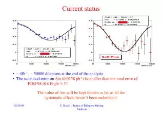
SR measurement w/ Single-Bunch HER 15 mA, with adjusting trigger timing Can measure dose w/ hit-rate (0.2 % occupancy) and energy deposition (15 keV/ch) ~20 kRad/yr dose @ 1.1 A (33 kRad/yr at max. position, f=180deg) ( contribution below th. is corrected by simulation) SVD 1.X SVD 2.0 data simulation
SVD Cluster Energy Spectra in Single Beam Run Can extract SR from spectrum shape !? HER 0.8 A LER 1.5 A SR and Particle-BG Only Particle-BG
E-spectrum of HER Particle-BG • Diff. btw vacuum • bump on/off in HER • LER 1.5 A HER E-spectrum of particle BG is same as LER !! #clusters/keV/event Can measure SR and particle-BG separately energy (keV)
Extraction SR in HER Single Beam HER Particle SR 50 mA 200 mA 100 mA Hard-SR simulation 400 mA 600 mA 800 mA
Correlation with Vacuum NSR a I(A) Nparticlea I(A) x P(Pa) Nparticle/NSRa P(Pa) Average of HER whole ring Average of HER upstream
Azimuthal Distribution of SR Single-Bunch 15 mA (trigger-timing is adjusted) Total 0.8 A w/ 1284 bunch (random timing) Hard-SR simulation 33 kRad/yr at HER 1.1A 21 kRad/yr at HER 1.1A simulation 29 kRad/yr Only above threshold 10 keV Simulation complements below thereshold
Azimuthal Distribution of Particle BG 44 kRad/yr at HER 1.1A simulation 53 kRad/yr HER 0.8 A 43 kRad/yr at LER 1.6A simulation 21 kRad/yr LER 1.5 A
Study of Touschek Effect Smaller beam-size (larger density) larger background Touschek contribution < 20 % at collision ~ 50 % at single beam 31 % in simulation Touschek contribution must be corrected If no Touschek Collision run Single beam run
Azimuthal Distribution of Particle BG 44 kRad/yr at HER 1.1A simulation 53 kRad/yr HER 0.8 A 22 43 kRad/yr at LER 1.6A simulation 21 kRad/yr LER 1.5 A 18
Radiation Dose at SVD 1st layer At Maximum Currents: HER 1.1A, LER 1.6A (…) is simulation @ 1nTorr pressure Touschek contribution is reduced based on measurement Data and simulation is consistent
Radiation Dose at SVD 1st layer At Maximum Currents: HER 1.1A, LER 1.6A (…) is simulation @ 1nTorr pressure • Two parameters have large uncertainty • (pressure, movable mask) • It may happen that absolute values too well agree • Consistency of azimuthal distribution is important Touschek contribution is reduced based on measurement Data and simulation is consistent
Radiation Dose at SVD 1st layer At Maximum Currents: HER 1.1A, LER 1.6A (…) is simulation @ 1nTorr pressure • We can trust simulations • Its uncertainty for abs. may be factor a few Touschek contribution is reduced based on measurement Data and simulation is consistent
Constraint for Occupancy (hit-rate) Radiation Dose Occupancy (cluster size: Particle-BG 3.5 ch, SR 1.5 ch) At Maximum Currents (HER 1.1A, LER 1.6A) Collision 12 % 11 %
Energy spectra for each layers 1st r ~ 2cm 2nd r ~ 4.4cm 3rd r ~ 7cm 4th r ~ 8.8cm LER single beam HER single beam
Layer dependence (single beam) Particle (LER) Particle (HER) SR BG a 1/(r-rbp), rbp: beampipe radius There may be correlation BG and 1/(r-rbp)
Other sub-detectors No large difference for BG (current diff. causes small diff. ?) No problem
Ideas for Less BG Particle-BG • Improvement of vacuum • HER: sensitive area is upstream (0~100 m) • LER: sensitive area is whole ring • How about not-straight path ? • HER upstream is almost straight path • Movable mask study 1/2 Particle-BG ~ 2/3 total-BG/Occ. SR-BG (dominated by Hard-SR) • Put photon-stop far place • Detail will be discussed in “Belle SR” talk
Summary Super-B • Beampipe radius 2 1.5 cm ( 1 cm) • Dose level is smaller (100 80 kRad/yr)Consistent with simulation • Measure SR & Particle-BG separately using energy spectrum of SVD SR contribution ~1/3 of total • Touschek is low < 20 % of LER-BG • BG may decrease a 1/(r-rbp) This method is first time in the world !? Success of beampipe design Strong support for design in Super-B
Radiation Monitors 18 kRad/yr 80 kRad/yr 60 kRad/yr before 100 kRad/yr Dose on Si is consistent with monitor
Is monitors measuring SR ? BWD FWD Outer-side of ring e- Be pipe Backscattered Hard-SR Inner-side of ring The 300 mm Au on the manifold blinds SR-BG Most of SR photons are absorbed by Au, and converted to lower energy photons (8~14keV) via the photoelectric effect Difficulty to measure SR Dose at DSSD center is same ? Measure BG by DSSD itself
Very Rough Estimation of Dose We can measure dose using its energy deposition - Occupancy ~ 10 % - Energy Deposition ~ 46 keV/ch - Bunch cycle 10 usec - Shaping time 2.6~3.0 usec ~100 kRad/yr - No subtraction of electrical noise, bad-ch effect - Contribution below threshold (~15keV) is not considered - Need to consider below th. for SR (low energy should be dominated by SR) Must measure for each components
SVD Hit Occupancy (hit-rate) • 1st layer (R=2 cm) 10~12 %(HER 1.1A, LER 1.6A) • Before (R=2.5 cm) 7 ~ 8 %(HER 1.0A, LER 1.5A) • 2nd layer (4.3 cm) ~ 4 %, 3rd, 4th layer ~ 2 %
SVD 2.0 SVD 1.6 beampipe radius SVD Occupancy (hit-rate) Large diff. of occ. btw 1st – 2nd layers may come from 1/(r-rbp) relation
Single Bunch like Run HER 15 mA, with adjusting trigger timing SVD 1st layer occupancy ~ 0.2 % corresponds to ~ 4 % occupancy @ 1.1 A Energy deposition 15.2 keV/ch corresponds to ~20 kRad/yr dose @ 1.1 A (33 kRad/yr at maximum position, f=180deg) ( contribution below th. is corrected by simulation) SVD 1.X SVD 2.0 data simulation
Correlation with Vacuum (Nparticle/NSR) / P(Pa) = const Upstream Pressure Average Pressure
Background at Collision Total dose Particle-BG SR-BG Run1560 (threshold ~15 keV) HER : 1.1 A, LER : 1.6 A 71 kRad/yr 11 kRad/yr Consistent with expectation from single-beams
Study of Touschek (life-time) Smaller beam-size (density) shorter life-time and larger background Touschek contribution < 20 % at collision ~ 45 % at single beam 42 % in simulation If no Touschek 1.4A 1.1A Touschek contribution must be corrected Collision run Single beam run 1/t abeam-density
Layer dependence (collision run) Particle-BG SR-BG BG a 1/(r-rbp) Large difference of occupancy btw 1st and 2nd layer BG comes from beampipe radius ?
Is there reasonable reason to explain 1/(r-rbp) correlation? Spent particles are scattered thin-Ta region Large contribution comes from here (simulation) Ta Be pipe Ta e- Be pipe Backscattered Hard-SR SR is scattered / absorbed at Au coating