Download
1 / 38
380 likes | 394 Vues
This presentation covers the components, requirements, and performance aspects of the LHCb Muon Detector system, including efficiency, aging studies, and production status. Wander Baldini from INFN-Ferrara details the structure, readout rates, and operational parameters of the system. The discussion includes the front-end electronics, drift velocity, readout schemes, and prototype testing results. The key focus is on meeting high-detection efficiency, time resolution, rate capability, and aging resistance criteria for robust operation over a period.

E N D
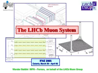
The LHCb Muon System IFAE 2005 Catania, March 30 – April 02 Wander Baldini INFN – Ferrara, on behalf of the LHCb Muon Group
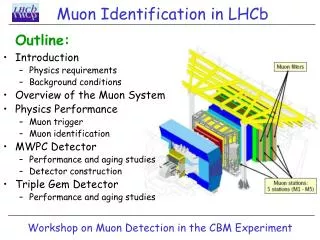
Overview • The LHCb Muon Detector • Requirements • Performances: • Detection Efficiency and time resolution • Ageing studies • Production status • Conclusions Wander Baldini, INFN-Ferrara
The LHCb Muon Detector R4 R3 ¼ of M4 station R1 R2 • 5 muon stations, one upstream (M1), 4 downstream (M2-M5) the calorimeters. • Each station is divided in 4 Radial Regions R1,R2,R3,R4 • The muon detector must provide high-pt information to the Level-0muon trigger througha • coincidence of hits in all five stations within the bunch crossing time of 25 ns • The muon momentum must be measured with δpt /pt ~ 20% accuracy. Wander Baldini, INFN-Ferrara
M4 M5 M3 M2 M1 RPC MWPC GEM The LHCb muon detector • 1380 MWPC chambers, total surface: 435 m2 • 12 triple GEM detectors for the highest rate region • Dimensions scales according to a pointing geometry • M2-M5: 4-gaps, M1: 2-gap Wander Baldini, INFN-Ferrara
Rates and Readout Rates (KHz) Detector type Readout Expected rates considering σpp= 102.4 mb including safety factors Wander Baldini, INFN-Ferrara
Requirements • High detection efficiency (> 99%) per station in a 20 ns time window: • good time resolution • Good rate capability: • up to ~460 kHz/cm2 @ L = 5•1032 cm–2 s-1 in hottest region; • fast • Aging resistant: up to an integrated charge ~ 1 C/cm • for safe operation in 10 years @ <L> = 2•1032 cm–2 s-1 • robust
MWPC design • 4 wire layers ( High detection efficiency + redundancy) • 5 mm symmetric gas gap • 2 mm wire pitch ( gold plated tungsten wires, 30 μm diameter ) • Wire tension: > 50 g 2layers are wire OR- ed in one FE channel HV HV HV HV 4 separate HV channels supplies the anode wires Structural Panel (poliuretanic foam) Gold plated cathode pads Solid gold plated Cathode Wander Baldini, INFN-Ferrara
Drift velocity: MWPC operating parameters: • Gas mixture: Ar / C02 / CF4 (40:40:20) • Working point: Gain~ 5•104 • total charge per gap: 53 e- (gap 5.0 mm) • Field on wires: 212 kV/cm, field on cathodes: ~ 5 kV/cm • Drift volocity: ~90 μm/ ns Total charge per mip: 0.4 pC (for cathode pads readout) collecting time @ half wire pitch: ~ 10 ns Wander Baldini, INFN-Ferrara
MWPC readout schemes • The readout scheme depends on the granularity requested by: trigger, offline and • particle rate • We have: anode wire readout, cathode pads readout and combined readout • (anode wire + cathode pads) R3: cathode pad readout R4: wire pad readout R1/R2-M2/M3: mixed readout Granularity goes from (1x2.5)cm2 to (25x30) cm2 MWPC dimensions from (48x20)cm2 to (149x31)cm2 Wire strip Wander Baldini, INFN-Ferrara
A small MWPC prototype: Closing bars (FR4) Gold plated cathode pads Panel (poliuretanic foam) 4 gaps Wander Baldini, INFN-Ferrara
M2R1 prototype (mixed readout) M2R4 – wire readout Photos M3R3 – cathode readout ~ 15 prototypes built and tested with (almost) final front-end electronics at the T11 test beam area at CERN. Wander Baldini, INFN-Ferrara
The Front-End Electronics: the CARIOCA chip Carioca is the Amplifier-Shaper-Discriminator front-end chip developed for the MWPCs of LHCb • Specifications important for time resolution • and rate capability: • Sensitivity: 15mV/fC • Short peaking time: • tp ~ 10 ns for Cdet = (40220) pF • Low noise: • ENC ~ 2000 e-/pF • High rate capability: • pulse width ~ 50ns, signal tail cancellation • and baseline restoration circuits. • 8 amplifiers per chip – 2 chips per board Wander Baldini, INFN-Ferrara
ε(double gap) 95% in 20 nsrms (double gap) 5 ns • HV(ε=95%) = 2.45 kV for wire readout • HV(ε=95%) = 2.55 kV for cathodes/mixed readout Efficiency and time resolution rms = 3.5 ns rms = 4.3 ns rms = 7.4 ns Cathode readout Cathode readout Wander Baldini, INFN-Ferrara
Time Resolution and Efficiency Uniformity: Example of uniformity measurements on a M3R3 prototype with cathode pad readout Time resolution: Double Gap Efficiency in 20 ns: 95 % 5 ns HV = 2.6 kV Pad number Pad number Average ε = (96.7 ±0.1) % Average time = (4.30.2) ns > 99% pads are inside the specifications Wander Baldini, INFN-Ferrara
High Rate behavior Test @ GIF up to 500 kHz/FEE channel Time resolution stable no space charge effect ~ 2% Small Efficiency drop due to signal pile-up Wander Baldini, INFN-Ferrara
Aging Test of MWPCs - Q < 10 mC/cm for 76% of area - 10 mC/cm <Q < 100 mC/cm for 19% of area - 100 mC/cm < Q < 1 C/cm for 5% of area Expected Integrated charge in 10 years @ 2•1032 cm-2 s-1 Particle rates are from LHCb-Muon TDR2001. Safety factors of have been included to take into account the deposited charge of low energy background hits. Wander Baldini, INFN-Ferrara
LNF,CERN1, CERN2 P ~0.3 Gy/hr T PC HV 4.5 m Co60 window CONTROL ROOM Aging tests @ ENEA Casaccia Calliope Facility: • Source: 60Co (~ 1015 Bq) • <Eγ> ~ 1.25 MeV • 3 MWPC irradiated with dose rates • up to ~ 0.3 Gy/hr and different gas • flows (vented and re-circulating • gas system) • Standard mixture: • Ar / C02 / CF4 = 40:40:20 • Gas gain ~ (11.5) 105 (~double wrt • to the nominal one). Wander Baldini, INFN-Ferrara
Aging tests @ ENEA Casaccia Calliope Facility • 32 days of tests • Integrated charge per cm of wire: • Q ~ (440480) mC/cm (510) years depending on the rate evaluation. • Typical current density: I ~ (1÷1.4) µA/cm2 (active areas = 500÷1200 cm2); • In each chamber, one gap (out of 4) was switched on only for short • periods to be used as reference Integrated Charge: test gaps Reference gap Wander Baldini, INFN-Ferrara
Current ratios – vented mode Current ratios - closed loop ~ 4% ~ 8% Aging tests @ ENEA Casaccia Calliope Facility We normalized the currents of tested gaps respect to the reference gap in order to remove T and P dependence and accidental gas mixture changes. Current ratios are constant within ~10% for all chambers. Malter currents: The self-sustaining rest currents were measured withthe sourceoff, using current monitors with a resolution of 1 nA. All gaps of all chambers drew currents of the order of few tens of nA or smaller with a decreasing trend. Wander Baldini, INFN-Ferrara
Analysis of Wires Photo 0 Wires are clean Wander Baldini, INFN-Ferrara
Boundary of FR4 etching Etching of the FR4 frame: Photo 1 The FR4 is etched also where there is no electric field. This effect is visible also in the reference gap : due to ionized gas fluorine etching. Wander Baldini, INFN-Ferrara
The etching of the FR4 frame goes with the gas flow : Gas flow direction: B1 B2 A2 A1, B1=reference gap B1 gap, “gas in”side B2 gap, “gas out” A2 gap, “gas in” …FR4 etched.. No etching…. ...Etching starts… B1 gap, “gas out” A2 gap, “gas out” B2 gap, “gas in” …No etching yet… …No etching…. ..FR4 etched!! Wander Baldini, INFN-Ferrara
Conclusions on the MWPC ageing test • In 32 days we integrated up to Q~480 mC/cm corresponding to • 510 years (depending on the rates foreseen) of LHCb • @ 2 x 1032 cm-2 s-1 • Materials exposed to CF4 under irradiation show a surface etching BUT no drop in gas gain observed within 10%: • we decided do not change chamber design and materials Wander Baldini, INFN-Ferrara
MWPC Chamber Production • A total of 1380 MWPC (+ 10%spare) have to be produced • The MWPC are produced in 6 productions centers: • LNF, Ferrara, Firenze, CERN, PNPI-1,PNPI-2 • LNF,PNPI-1,CERN started in January 2004, Ferrara and Firenze in August 2004, PNPI-2 is starting now Wander Baldini, INFN-Ferrara
PNPI-1 LNF CERN Production status FERRARA FIRENZE Wander Baldini, INFN-Ferrara
Conclusions • Three years of extensive tests showed that our design of MWPCs of operating with CF4 based gas mixture satisfies all the requirements for the LHCb Muon System • We built a fast detector, with good time resolution and aging resistant • It will cover an area of ~ 435 m2 with 1380 chambers and ~126000 readout channels • The production is started and the detector should be ready for the 1st LHC beams Wander Baldini, INFN-Ferrara
Spares: Wander Baldini, INFN-Ferrara
2.6 kV Efficiency in 20 ns Crosstalk in 20 ns TW ~4% Efficiency and crosstalk Crosstalk: probability of firing the neighboring pad Pt accuracy measurement requires: Crosstalk < 5% Main source is the pad-to-pad capacitive coupling Wander Baldini, INFN-Ferrara
Chambers materials Common Materials: Gold plated 30 μm tungsten wires. Gold platedcathode pads. Adekit 145/450 epoxy for wire glueing. INFN CHAMBERS INFN chamber: • Adekit 140 for chamber closing. CERN CHAMBERS CERN chambers: • Natural rubber O-rings. • Kapton foils to protect HV-traces and glued with epoxy. • Low temperature soldering, carbon film resistors and SMD capacitors. Wander Baldini, INFN-Ferrara
RPC for LHCB Muon System Historical review 1998: RPC were proposed for LHCb Muon detector in regions with rates < 1 kHz/cm2. 1999: 2 prototypes built with identical characteristics: - bakelite electrodes (ρ ~ 1010 Ω cm); - linseed oil; - graphite ( 100 kΩ/) ; - 50 x 50 cm2 area. - 2 mm gas gap (C2H2F4 : iC4H10 : SF6 = 95:4:1) - avalanche mode (HV ~10.6 kV). 2000: rate capability was measured to be 3 kHz/cm2 (NIM A 456 (2000) 95.) 2001: an extensive test for study the aging properties started at GIF… Rates (kHz/cm2) and integrated charge (C/cm2) for L = 5•1032 cm-2 s-1 RPC Wander Baldini, INFN-Ferrara
Aging test in 2001 @ GIF GIF test setup RPC A (high flux):QA~0.4 C/cm2 RPC B (low flux): QB~ 0.05 C/cm2 • RPC A irradiated at GIF during 7 months up to Q~ 0.4 C/cm2 . • RPC B not irradiated, used as reference. • I, V0 and T continuously monitored. • Bakelite resistivity ρ extracted from (I,V0) curve using a model for RPC operating under high flux conditions ( NIMA 498 (2003) 135) and corrected for T dependence. Wander Baldini, INFN-Ferrara
Aging test in 2001 @ GIF: RPC A results ρ~ 70 1010 Ω•cm Q ~ 420 mC/cm2 dec01 ρ (T=20°) (10 10 Ω•cm) Integratedcharge (mC/cm2) ρ~ 40 1010 Ω•cm aug01 mar01 ρ~ 6 1010 Ω•cm jan01 month irradiation no irradiation Observed a steady increase of ρ with and without irradiation. Wander Baldini, INFN-Ferrara
RPCA RPCB ρ ~ 200 •1010 Ωcm ρ ~ 220 •1010 Ωcm ρ ~ 10 •1010 Ωcm Aging test in 2002 @ GIF • Both detectors slowly irradiated ( Q~0.05 C/cm2 accumulated charge ). • Resistivity continuously measured during ~ 350 days. • Observed a steady increase of ρ with time for both deterctors probably due to drying up of bakelite. • Addition of 1.2% of H2O vapor to the nominal gas mixture produced a decrease of resistivity. This effect in any case disappeared as soon as dry gas was flowed. ρ ~ 70 •1010 Ωcm H2O vapor H2O vapor Wander Baldini, INFN-Ferrara
Mechanical Tolerances: • The specifications for a single gap were defined such as the gas gain • is within : • - 0.8*G0 and 1.25*G0 in 95% of the chamber area; • - G0/1.5 and 1.5*G0 in 5% of the chamber area. • What chamber imperfections are allowed in order to keep the gain within • specifications? • SPECIFICATIONS: • • Gap: 95% in 90 µm 5% in 180 µm • • Wire pitch: 95% in 50 µm 5% in 100 µm • • Wire y-offset: 95% in 100 µm 5% in 200 µm • • Wire plane y-offset: 95% in 100 µm 5% in 200 µm • The most critical parameter for our chambers is the gap dimension !! Wander Baldini, INFN-Ferrara
A: B: 137Cs source 137Cs source Lead case Lead case D: MWPC C: Measurement of gain uniformity: -We scan each gap using a radioactive source (137Cs, 40 mCi, 0.66 MeV photons). -The current drawn by group of wires is measured by a nano-amperometer with 1 nA resolution. ~ good good ~ good very good Wander Baldini, INFN-Ferrara
Average ratesand Integrated Charges: kHz/cm2 mC/cm • - Rates (TDR2000) and integrated charges in 10 equivalent (~ 108 s) years for average luminosity <L> = 2 • 1032 cm-2 s-1 , • Safety factors (2 in M1 and 5 in M2-M5) are included. Wander Baldini, INFN-Ferrara
Comparison with simulations • Comparison with simulations has been done • by plotting double gap efficiency and • time resolution as a function of threshold. • The threshold is expressed as a fraction of • the average signal in order to be independent • from the gain. • Full simulation: • - primary ionization (HEED); • - drift, diffusion (MAGBOLTZ); • - induced signals (GARFIELD). Good agreement between data and simulations Wander Baldini, INFN-Ferrara
Comparison with ATLAS/CMS The ATLAS Cathode Strip Chambers are intended for position resolution. Amplifier peaking time 80ns, bipolar shaping, ‘crosstalk intended’ on cathode strips for center of gravity. The CMS Cathode Strip Chambers are intended for position resolution (cathodes strips) and timing (wires). Cathode amplifier peaking time 100ns, wire amplifier peaking time 30ns. The LHCb MWPCs are intended for highly efficient timing within a certain spatial granularity at the LVL0 trigger. Amplifier peaking time of 10ns, pulse width<50ns, unipolar shaping, low crosstalk. Since crosstalk is RinCpp and since (20 MHz) is high we have to minimize the pad-pad capacitance Cpp and amplifier input impedance Rin. Because we want unipolar shaping we need a baseline restorer in the front end. Wander Baldini, INFN-Ferrara