Fluid Systems
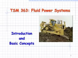
Lesson 5. Fluid Systems. Fluid Systems . Water under pressure is used in many applications such as hydroforming ( the process of using water under high pressure to shape metal components)

Fluid Systems
E N D
Presentation Transcript
Lesson 5 Fluid Systems
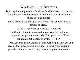
Fluid Systems • Water under pressure is used in many applications such as hydroforming • (the process of using water under high pressure to shape metal components) • and water jet cutting (the process of using water under high pressure and at a high cut speed to cut manufactured products
Volume flow rate • The volume per second of a fluid flow; symbol qv. • The equation is , where qv is the volume flow rate, V is the volume, and ∆t is the time interval
Example 1 • The volume flow rate needed to cut a material component is 3.3 L/min, and the time interval required is 18 s. Calculate the total volume of water used during this process. • qv= 3.3 L/min = 0.055 L/s • ∆t = 18 s • V =?
V = ∆t x qv • V = (18 s) x (0.055L/s) • V = 0.99L • Therefore the total volume of water needed is 0.99 L.
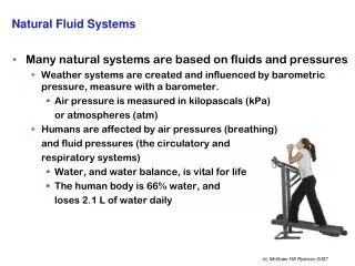
The speed of a fluid flowing through a pipe can also be an important piece of information. • Whether plumbing a house, or putting out a fire. The flow rate can be vital information.
The formula to find the speed can be derived from equation for flow rate: the total volume in a pipe of length l is Al, where A is the cross sectional area of the pipe. • Thus
Example 2 • Calculate the speed of water in a pipe of radius 0.21 mm if the volume flow rate of water is 6.0 x 10⁻⁶ m3/s • qv= 6.0 x 10⁻⁶ m3/s • r = 0.21 mm = 2.1 x 10⁻⁴ m • A = πr2 • A = π(2.1 x 10⁻⁴ m)2 • A = 1.385 x 10⁻⁷ m2 • v = ?
v = 43 m/s • Therefore, the speed of the water is 43 m/s
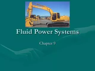
Fluid System Schematic Diagrams • The initial source of energy for the systems can be an electric motor or other device that drives a pump for liquids (liquids) or a compressor (gases). The pump or compressors transforms mechanical forces into fluid forces. The final output of the system is the actuator, a device that transforms fluid forces back into mechanical forces. • All of the components in a fluid system must form a circuit in which the fluid can flow.
Symbols are used to draw circuit diagrams of fluid systems. The following symbols are commonly used in fluid system diagrams.
Transmission lines – the pipe through which the fluid travels • -continuous line - flow line • -dashed line - pilot, drain
Circular • -large circle - pump, motor • -small circle - Measuring devices • -semi-circle - rotary actuator
Diamond • - Fluid conditioner (filter, separator, lubricator, heat exchanger)
one square - pressure control function • two or three adjacent squares - directional control
Triangle • -solid - Direction of Hydraulic Fluid Flow • -open - Direction of Pneumatic flow
Single acting cylinder • -returned by external force • -returned by spring or extended by spring force
Miscellaneous Symbols • Spring • Flow Restriction
Double acting cylinders • -single piston rod (fluid required to extend and retract) • -double ended piston rod
Directional control valve (3 ports / 2 positions) • -Normally closed directional control valve with 3 ports and 2 finite positions • -Normally open directional control valve with 3 ports and 2 finite positions.
Manual Control • -general symbol (without showing the control type) • -pushbutton • -lever • -foot pedal
Mechanical Control • -plunger or tracer • -spring • -roller • -roller(one direction only)
Questions • During hydroforming, a force of magnitude 1.8 x 10⁶ N is applied to a piece of steel 12 cm x 14 cm. Calculate the pressure, in pascals and kilopascals on the piece of steel. T(1) C (1) • In a water jet cutting process, a stream of water with the speed 1.6 x 10² m/s drills a hole of radius 0.28 mm with a force of magnitude 1.2 x 10² N. The process lasts for 16 s. Calculate. • The pressure, in pascals of the water on the metal . T (1) • The volume flow rate of the water T (1) • The total volume of water used in the process, in cubic meters. T (1)
What are the main uses of valves in a fluid system? C (1) • Name and draw the circuit for the type of device that controls : C (2) • A hand-held sprinkler • The hand pump used to inflate a tire. • Would you recommend a hydraulically operated or a pneumatically operated robot that needs to respond quickly and efficiently to all types of loads and must operate at many temperatures. T (1) C (1)