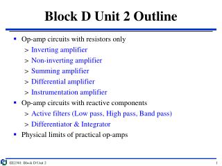
Block A Unit 1 Outline
Block A Unit 1 Outline. Concepts Charge & Current; Voltage; Resistance; Power Terminology Branch, Mesh, Node Laws Kirchhoff’s current and voltage laws; Ohm’s law Resistive networks Parallel and series; current and voltage divider rule Measuring instruments (application)

Block A Unit 1 Outline
E N D
Presentation Transcript
Block A Unit 1 Outline • Concepts • Charge & Current; Voltage; Resistance; Power • Terminology • Branch, Mesh, Node • Laws • Kirchhoff’s current and voltage laws; Ohm’s law • Resistive networks • Parallel and series; current and voltage divider rule • Measuring instruments (application) • Ammeters and Voltmeters Block A Unit 1
Electric Charge • Charge is a fundamental electric quantity, measured by the unit Coulomb (C) • The smallest amount of charge that exists is the charge that is carried by 1 electron = -1.602 x 10⁻¹⁹ C • Therefore charge quantities in real life occur in integral multiples of an electron’s charge • Typically denoted by the symbol Q Block A Unit 1
_ _ _ _ _ _ _ _ _ _ _ _ _ _ _ _ _ _ _ _ _ Current: Free electrons on the move + - Currents must run in loops Direction of current Current in relation to Charge • Currents arise from flow of charges • Unit: Ampere (A) • Typically denoted by the symbol, I • Current = Rate of change of charge • Mathematically, I = dQ/dt Conventional current flows from + to - (Opposite direction to electron flow) Block A Unit 1
Fundamental law for charge • Current has to flow in closed loop • No current flows if there is a break in the path • Underlying physical law: Charge cannot be created or destroyed • This is the basis of Kirchhoff’s Current Law i1 Kirchhoff’s current law Sum of currents at a node must equal to zero: i1 + i2 + i3 + i4 = 0 i2 i4 i3 Block A Unit 1
Kirchhoff’s current law Does the direction of current matter? YES!! I2 running into node I2 running out of node i1 i1 Different i2 i2 i3 i3 i1 + i2 + i3 = 0 (WRONG) i1 + i2 + i3 = 0 i1 + i3 = i2(CORRECT) Block A Unit 1
Kirchhoff’s current law Currents EXITING (-ve), Currents ENTERING (+ve) Sign convention when applying KCL i1 Entering: I1 & I2 (+ve) Exiting: I3 & I4 (-ve) i2 i4 i1 + i2 – i3 – i4 = 0 i3 Block A Unit 1
KCL example Problem 2.14 and 2.15 Find the unknown current using KCL 6A - 5A + 2A - i = 0 i = 3A 6A - 5A + 2A + i = 0 i = -3A Block A Unit 1
_ _ _ _ _ _ Voltage/Potential difference Current A B Unit: Volt (V) vx = vA - vB vx +- High (+) Energy is required to move charges between 2 points Voltage/potential difference is always made with reference to 2 points Direction of Flow Low (-) Block A Unit 1
Sign convention In a LOAD Voltage DROPS in the direction of the current Energy is dissipated (or consumed) i v + - In a SOURCE Voltage RISES in the direction of the current Energy is generated i +- v Block A Unit 1
Fundamental law on voltage • Energy is required to push electrons through a resistive element • That same energy needs to be generated by a source • Total energy generated in a circuit must equal total energy consumed in the circuit • Energy cannot be created or destroyed • Therefore, voltage rise = voltage drop - V3 + Kirchhoff’s voltage law Net voltage around a closed circuit is zero: v1 + v2 + v3 + v4 = 0 + V2 - - V4 + + V1 - Block A Unit 1
Kirchhoff’s voltage law • Reference voltage in a circuit set to 0V • All other nodes on the circuit can then be conveniently referenced to GROUND load + V2 - DEFINING signs • Voltage gain (+ve) • Voltage drop (-ve) + V1 - source load v1 – v2 + v3 = 0 + V3 - load Ground symbol GROUND Block A Unit 1
KVL example Problem 2.16 Apply KVL to find voltage V1 and V2 Loop 1 (Clock-wise): 5V - 3V - V2 = 0 V2 = 2V Loop 2 (Anti-clock-wise): V1 - 10V - V2 = 0 V1 = 12V Block A Unit 1
Resistance and Ohm’s Law I i Ideal RESISTOR shows linear resistance obeying Ohm’s law + v _ 1/R Unit: Ohm (Ω) V When current flows through any circuit element, there will always be a resistance to its flow which results in a voltage drop across that circuit element Ohm’s law: V = IR A L IMPORTANT: Positive current is defined here as flowing from higher to lower voltage (Remember) ρ: resistivity (material property) A: cross-sectional area Block A Unit 1
Ohm’s law + KCL example Problem 2.17 Use Ohm’s law + KCL to find the current through the 15Ω resistor KCL: I1 + I2 = 10A Ohm’s: 15I1= V15Ω (1); 30I2 = V30Ω (2) (KVL) V15Ω = V30Ω Therefore, 2I2 = I1 Solving for the variables: I2 = 3.33 A, I1 = 6.67 A Block A Unit 1
Electrical Power Electrical power generated/dissipated in a given element is defined by the product of the voltage across that element and the current through it • In a source, power is generated • In a load (eg. resistor), power is dissipated/consumed Unit: Watt (W) P = VI + + 0.2A 1.5V 0.2A P = I2R P = V2/R 1.5V _ _ Source: P = 1.5V x 0.2A = 0.3W Load: P = 1.5V x 0.2A = 0.3W Power generated by source MUST EQUAL Power dissipated in the load Block A Unit 1
Power example Problem 2.22 Determine which components are absorbing power and which are delivering power Is conservation of power observed in this example? Block A Unit 1
Power example solution Finally calculate power through each element A: (12V)(5A) = 60W [generating] B: (3V)(5A) = 15W [generating] C: (-5V)(5A) = -25W [absorbing] D: (-10V)(3A) = -30W [absorbing] E: (-10V)(2A) = -20W [absorbing] Last part: “Is power conserved?” Generating: 60W + 15W = 75W Absorbing: 25W + 30W + 20W = 75W YES! This slide is meant to be blank Block A Unit 1
Terminology: Branch and Node BRANCH: Any path of a circuit with 2 TERMINALS connected to it Branch Node NODE:Junction of 2 or more branches Block A Unit 1
Terminology: Loop and Mesh + - Vs LOOP: Any closed connection of branches In the above circuit, there are 6 loops in total + - Vs Mesh: Loop that does not contain other loops In the above circuit, there are 3 meshes in total Block A Unit 1
DC vs AC • DC– Direct Current: Current is constant with time • AC– Alternating Current: Current varies with time and reverses direction periodically Block A Unit 1
Independent Voltage Source + + i + v v Circuit _ i _ _ Independent Voltage Source supplies a prescribed voltage across its terminals irrespective of current flowing through it Current supplied is determined by load circuit connected Block A Unit 1
Independent Current Source + + i i v Circuit i _ _ Independent Current Source supplies a prescribed current to any load circuit connected to it Voltage supplied is determined by load circuit connected Block A Unit 1
Dependent Sources • DEPENDENT source generates v or i that is a function of some other v or i in the circuit • Symbol – diamond shape outline +vx- +- 5V vs Independent + VoltageControlled Voltage Source (VCVS): vs = μvx CurrentControlled Voltage Source (CCVS): vs = rix _ VoltageControlled Current Source (VCCS): is = gvx CurrentControlled Current Source (CCCS): is = βix is Block A Unit 1
Example of a VCVS Ro +vi- Ri Avi + - Note: This is a general model for an amplifier which shall be re-visited later in BLOCK C Block A Unit 1
Short Circuit Short circuit: Connect 2 or more terminals so that the voltage between each of them is the same Typically associated with current, eg. short-circuit current A 0.1A 20Ω B Short circuit A & B 20Ω resistor is now bypassed Current from source flows through the short-circuit to give a short-circuit current A 0.1A 20Ω Isc B Short circuit current Isc = 0.1A Block A Unit 1
Open Circuit Open circuit: Leave 2 terminals unconnected externally Typically associated with voltage, eg. open-circuit voltage A 20Ω 0.1A B Ioc= 0A A + Voc - Open circuit voltage Voc = 0.1A × 20Ω = 2V 0.1A 20Ω B Block A Unit 1
Self-contradictory circuits A Prefixes: Memorize and apply them! +- vs B What is the voltage across A and B? A Is Write as 2.15mA instead of 0.00215A B What is the current arriving at A? Block A Unit 1
Parallel network (Highlights) I1 I2 IN R1 R2 RN RP Is Is Equivalent Resistance 1/RP = 1/R1 + 1/R2 + …+ 1/RN Current divider rule Block A Unit 1
Parallel Network: Proof I2 X Apply Kirchhoff’s current law (KCL) at X: Is = I2 + I1 I1 R1 R2 Is This can be seen as Is is split into the 2 branches I2 1 2 3 X Note that points 1, 2, 3 are all at the same voltage, therefore same node (X) Points 4, 5, 6 are all at the same voltage, therefore same node (Y) Voltage across R1 = Voltage across R2 = VXY I1 R1 R2 Is 4 5 6 Y Block A Unit 1
Parallel network: Proof Apply Ohm’s to both R1 and R2: VXY = I1R1 = I2R2 I1 = VXY/R1; I2 = VXY/R2 I2 1 2 3 X I1 R1 R2 Is Adding I2 & I1 up according to KCL: Is = VXY(1/R1 + 1/R2) 4 5 6 Y We can now find how much of Isis distributed between the 2 branches This is referred to as the current divider rule Block A Unit 1
Parallel network: Proof I2 Is = VXY(1/R1 + 1/R2) I1 R1 R2 Replace the parallel network of resistors with a single equivalent resistor Is Remember that the voltage across RP is still VXY! X VXY/RP = VXY(1/R1 + 1/R2) RP Is 1/RP = 1/R1 + 1/R2 Y Block A Unit 1
Parallel network (seeing it) Current splits at one node I1 I2 IN R1 R2 RN Is Current re-combine at the other node Suggestion: Think about parallel resistors as the rungs on a ladder Block A Unit 1
Current divider: Example 1 V1 • Find i1 and i2 in terms of I • If R1 = R2, find the ratio between i1 and i2 • If R2 = 3R1, find the ratio between i1 and i2 I i1 R1 i2 R2 i1 = [R2 / (R1 + R2)]I; i2 = [R1 / (R1 + R2)]I V2 If R1 = R2, then i1 = i2 = I/2 If R2 = 3R1, then i1 = 3I/4, i2 = I/4 Therefore i1 = 3i2 Block A Unit 1
Current divider: Example 2 • Find the current through each resistor in terms of I • Find the current through each resistor in terms of I if a 4th resistor was added in parallel • How many resistor are required to reduce the current in each resistor to 1% of I (ie 1/100) V1 I i1 R i2 R i3 R V2 i1 = i2 = i3 = I/3 i1 = i2 = i3 = i4 = I/4 Consider that, in = I/n Hence n = 100 for in = 0.01I Block A Unit 1
Current divider: Example 3 V1 If R2 > R4 > R1 > R5 > R3 • Which current is the largest? • Which current is the smallest? • Rank the currents from largest to smallest I i1 R1 i2 R2 i3 R3 i4 R4 i5 R5 V2 I3 > I5 > I1 > I4 > I2 Block A Unit 1
Series network (Highlights) + - R1 V1 +- RS Vs + - R2 V2 +- Vs Equivalent Resistance RS = R1 + R2 + …+ RN + - RN VN Voltage divider rule VN = VS(RN/RS) Block A Unit 1
Series network: Proof Apply Ohm’s law to both resistors: V1 = ISR1; V2 = ISR2 Adding up V1 and V2 according to KVL: Vs = IS(R1+R2) + - R1 V1 +- Vs + - R2 V2 Is We can now find how much of Vs is distributed between the 2 resistors This is referred to as the voltage divider rule Block A Unit 1
Series network: Proof Vs = IS(R1+R2) R1 +- Replace the series network of resistors with a single equivalent resistor Vs R2 Remember that the current going into RS is still IS! IsRS = IS(R1+R2) +- RS Vs RS = R1+R2 Block A Unit 1
Series network (seeing it) + - R1 V1 + - R2 V2 +- Vs + - RN VN Suggestion: Think about series resistors as the rings forming a chain Block A Unit 1
Voltage Divider: Example 1 • Find the voltage across each resistor • Find the voltage at nodes 1 and 2 2V 5V 10Ω 30Ω 20Ω Node 1 Node 2 Total resistance (in series) RT = 10 + 20 + 30 = 60Ω V10Ω = (1/6)(3) = 0.5V; V20Ω = (1/3)(3) = 1V; V30Ω = (1/2)(3) = 1.5V At node 1: V1 = 2 + 0.5 = 2.5V At node 2: V2 = 5 – 1.5 = 3.5V Block A Unit 1
Voltage Divider: Example 2 0V 9V R1 R2 R3 • If R3=3R1 and R2 = 2R1 • Find the voltage across each resistor • Find the voltage at nodes 1 and 2 Node 1 Node 2 VR1 = (R1/RT)(VB - VA) = 9/6 = 1.5V; VR2 = (R2/RT)(VB - VA) = 9/3 = 3V VR3 = (R3/RT)(VB - VA) = 9/2 = 4.5V At node 1: V1 = VR1 + VA = VB/6 At node 2: V1 = VB - VR3 = VB/2 Block A Unit 1
Voltage Divider: Example 3 If R2 > R4 > R1 > R5 > R3 • Which voltage difference is the largest? • Which voltage difference is the smallest? • Rank the voltage differences from largest to smallest + V1 - + V2 - + V3 - + V4 - + V5 - VA VB R1 R2 R3 R4 R5 V2 > V4 > V1 > V5 > V3 Block A Unit 1
Series-Parallel combo: Example 1 Find the total resistance as seen across A and B All resistors have value of 1Ω A A RAB = (R1 || R2) + (R3 || R4) = 1||1 + 1||1 = 1Ω R1 R2 R1 R2 R3 R4 RAB = (R1 + R3) || (R2 + R4) = 2||2 = 1Ω R3 R4 B B Block A Unit 1
Combo example 2 Problem 2.48 Find the equivalent resistance seen by the source How much power is delivered by the source? Combine the 1Ω and 2Ω in series: R1 = 3Ω Combine the R1 with 3Ω in parallel: R2 = 1.5Ω Combine the R2 with 4Ω & 5Ω in series: R3 = 10.5Ω Combine the R3 with 6Ω in parallel: R4 = 3.818Ω Combine the R4 with 7Ω in series: RT = 10.818Ω Power delivered by source: P = VS2/RT = 18.1W Block A Unit 1
Combo example 2 This slide is meant to be blank Block A Unit 1
Combo example 3 Problem 2.48 Find the equivalent resistance seen by the source Find the current through the 90Ω resistor Block A Unit 1
Combo example 3 This slide is meant to be blank Block A Unit 1
Power dissipation Power: P = V I Power dissipated in resistor R P = I2R = V2/R i R + V - Power dissipated: P = v22 / R2 R1 + +- Vs v2 R2 For Max Power Transfer: R1 = R2 _ Find condition for dP/dR2 = 0 (max pt) Block A Unit 1
Practical voltage source Motivation: The ideal source does not consider internal resistance of sources so we need to modify ideal model to describe the physical limitations in practical sources: Ideal voltage source in series with a source resistance Rs +- +- Vs RL Vs RL Ideal Practical Terminal voltage becomes: VRL = [RL/(RL+RS)]VS instead of VS VRL is now lower due to some voltage drop across RS Block A Unit 1
Practical current source Motivation: The ideal source does not consider internal resistance of sources so we need to modify ideal model to describe the physical limitations in practical sources: Ideal current source in parallel with a source resistance Is RL Is RL Rs Ideal Practical Current through the load now becomes: IRL = [Rs/(RL+RS)]IS instead of IS IRL is now lower due to a fraction of the source current flowing into RS Block A Unit 1