Download
1 / 25
250 likes | 399 Vues
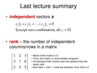
Quick Summary of Last Lecture Block A Unit 1. Three Basic Laws. Fundamental law for charge. Current has to flow in closed loop No current flows if there is a break in the path Underlying physical law: Charge cannot be created or destroyed This is the basis of Kirchhoff’s Current Law. i 1.

E N D
Quick Summary of Last LectureBlock A Unit 1 Three Basic Laws EE2301: Block A Unit 2
Fundamental law for charge • Current has to flow in closed loop • No current flows if there is a break in the path • Underlying physical law: Charge cannot be created or destroyed • This is the basis of Kirchhoff’s Current Law i1 Kirchhoff’s current law Sum of currents at a node must equal to zero: i1 + i2 + i3 + i4 = 0 i2 i4 i3 Block A Unit 1
Fundamental law on voltage • Energy is required to push electrons through a resistive element • That same energy needs to be generated by a source • Total energy generated in a circuit must equal total energy consumed in the circuit • Energy cannot be created or destroyed • Therefore, voltage rise = voltage drop - V3 + Kirchhoff’s voltage law Net voltage around a closed circuit is zero: v1 + v2 + v3 + v4 = 0 + V2 - - V4 + + V1 - Block A Unit 1
Resistance and Ohm’s Law I i Ideal RESISTOR shows linear resistance obeying Ohm’s law + v _ 1/R Unit: Ohm (Ω) V When current flows through any circuit element, there will always be a resistance to its flow which results in a voltage drop across that circuit element Ohm’s law: V = IR A L IMPORTANT: Positive current is defined here as flowing from higher to lower voltage (Remember) ρ: resistivity (material property) A: cross-sectional area Block A Unit 1
Parallel network (Highlights) I1 I2 IN R1 R2 RN RP Is Is Equivalent Resistance 1/RP = 1/R1 + 1/R2 + …+ 1/RN Current divider rule Block A Unit 1
Series network (Highlights) + - R1 V1 +- RS Vs + - R2 V2 +- Vs Equivalent Resistance RS = R1 + R2 + …+ RN + - RN VN Voltage divider rule VN = VS(RN/RS) Block A Unit 1
Let’s have a look first EE2301: Block A Unit 2
Block A Unit 2 outline • Applying the 3 laws to analyze DC circuits • Systematic methods for analysis • Nodal voltage analysis (application of KCL and Ohm’s law) • Mesh current analysis (application of KVL and Ohm’s law) • Superposition (can be a powerful tool) G. Rizzoni, “Fundamental of EE” Chapter 3.2 – 3.5 EE2301: Block A Unit 2
Nodal voltage analysis Nodal voltage analysis is simply an application of Ohm’s law and KCL together. Here we express branch currents in terms of voltage and resistance using Ohm’s law X V1 V3 Applying NVA at node X: R1 R3 R2 V2 This can be seen if we first consider currents in each branch arriving at X: Current from V1 to VX via R1 = (V1 - VX)/R1 Current from V2 to VX via R2 = (V2 - VX)/R2 Current from V3 to VX via R3 = (V3 - VX)/R3 Summing these together, we obtain the above final expression EE2301: Block A Unit 2
NVA example 1 Problem 3.1: Use nodal voltage analysis to find the voltages V1 and V2 1 Ω Solve for V1 and V2: V1 = 4.8 V, V2 = 2.4 V Apply KVL at V1: Apply KVL at V2: EE2301: Block A Unit 2
NVA example 2 Problem 3.4: Use nodal voltage analysis to find the current through the voltage source Apply KCL at V1: Apply KCL at V2: Apply KCL at V3: First, define and label the unknown nodes EE2301: Block A Unit 2
NVA example 2 solution There are now 3 equations but 4 unknowns; we need one more equation!! V3 - V2 = 3 Now, eliminate V3 from all 3 equations: V2 + (3 + V2) - 2V1 = 1 V1 - V2 = 1 Now, eliminate V2: This slide is meant to be blank EE2301: Block A Unit 2
Mesh current analysis Mesh current analysis is simply an application of Ohm’s law and KVL together. Here we express branch voltages in terms of current and resistance using Ohm’s law R1 R3 Apply KVL to each mesh in turn R2 Around Mesh 1: vs = i1(R1 + R2) - i2R2 Around Mesh 2: i2(R3 + R4 + R2) - i1R2 = 0 + i1 i2 R4 _ vs 0V • If the current direction is known, then the easiest choice is simply to follow it. This will avoid any confusion (e.g. in a voltage source, define the current as flowing in the direction of voltage gain) • Pay close attention to the direction of one mesh current to another (e.g. in this instance, i1 is flowing opposite to i2 hence we take the difference in R2 EE2301: Block A Unit 2
MCA example 1 Problem 3.30 Use mesh current analysis to find the current (i) through the 1/5 Ω resistor This slide is meant to be blank EE2301: Block A Unit 2
MCA example 1 solution Since I = i1, so only 2 unknown meshes to solve for KVL around mesh 2: KVL around mesh 3: Solving for I2 and I3: I2 = 20/31 A, I3 = 15/31 A Current through the 1/5 Ω resistor, i = i3 - i2 = - 5/31 = - 0.161 A This slide is meant to be blank EE2301: Block A Unit 2
MCA example 2 Problem 3.17 Use mesh current analysis to find the voltage across the current source Apply KVL around mesh 1: 2 = I1(2+3) - I2(3) 5I1 - 3I2 = 2 I3 Apply KVL around mesh 2: -V = I2(3+1) - I1(3) 4I2 - 3I1 = -V Apply KVL around mesh 3: V = I3(3+2) 5I3 = V EE2301: Block A Unit 2
MCA example 2 There are now 3 equations but 4 unknowns; we need one more equation!! 2 = I3 - I2 Substitute into mesh 3 to eliminate i3 and use this to eliminated i2 in mesh 2: Substitute into mesh 1 to find V: This slide is meant to be blank EE2301: Block A Unit 2
Principle of superposition Consider what happens when you throw a stone into a pool at A & B Only at A Only at B A B A B A B Both A and B together If the stones hit A and B together, the result will be a combination of the individual responses of A and B. This is the principle of superposition. EE2301: Block A Unit 2
I RG RB IB + VG - Superposition in circuits Say we want to find the current through RB INPUT OUTPUT SYSTEM A’ A B’ B A’+B’ A+B If we apply superposition, this current is the sum of the individual currents corresponding to each of the sources in the circuit, i.e. current associated only with VG or IB alone. That is to say, we need to remove the effects from all the sources except one, and find the corresponding value of I for this source. We then repeat this for the other sources. But how do we remove the effects of a certain source? EE2301: Block A Unit 2
+ - Disabling sources in superposition Voltage source: We want no voltage drop across Therefore replace with a short Current source: We want no current flowing through Therefore replace with an open circuit Vs IN I1 I2 RG RG RB RB Open circuit IB I = I1 + I2 + VG IB = 0 VG = 0 - Short circuit EE2301: Block A Unit 2
I RG RB IB + VG - Superposition in Circuits Find I VG = 0 IB = 0 I1 I2 RG RG RB RB Open circuit IB I = I1 + I2 + VG - Short circuit EE2301: Block A Unit 2
Superposition example 1 Problem 3.40 Determine, using superposition, the current through R1 due only to the source VS2 EE2301: Block A Unit 2
Superposition example 1 solution Re-drawn circuit due to VS2 only Note that now R1 || R2 are parallel • Suggested strategy: • Use voltage divider rule to find voltage across R1 • Use ohm’s law to find current through R1 This slide is meant to be blank EE2301: Block A Unit 2
Superposition example 2 Problem 3.41 Determine, using superposition, the voltage across R This slide is meant to be blank EE2301: Block A Unit 2
Superposition example 2 VR due to VG only: R and RB are parallel, which together are in series with RG Apply voltage divider rule: VR due to IB only: All 3 resistor are in parallel Adding the two solutions together: VR = 5.99V This slide is meant to be blank EE2301: Block A Unit 2