Analyzing the Image Density
Analyzing the Image Density . Density . Overall blackening of the image. Assessing Density . Anatomical area of interest OD 0.25-2.50 Darker image preferable to light image. Factors Affecting Density mAs. Controlling Factor

Analyzing the Image Density
E N D
Presentation Transcript
Density • Overall blackening of the image
Assessing Density • Anatomical area of interest • OD 0.25-2.50 • Darker image preferable to light image
Factors Affecting Density mAs Controlling Factor In the straight line portion of the sensitometric curve, density proportional to log relative exposure. mAs can be adjusted to compensate for changes made in other technical factors.
DensitymAs as Controlling Factor • Reciprocity Law • Density should remain the same as long as the same mAs is used regardless of the mA and time combination • Reciprocity Law failure • Occurs at short exposure times (less than .01) or long exposure times (several seconds)
DensitymAs as Controlling Factor • Minimum change 30% in exposure • Either 30% change in mAs or other factors that equal 30% change in exposure • For mAs changes, adjust in increments of 2 X or ½ mAs
BEWARE The “Step in Time”
DensityKilovoltage • 15% increase in kVp doubles the exposure to the film • 15% decrease in kVp halves the exposure to the film • In the lower kVp range (30-50), a change of 4-5 % in kVp may be detectable; in the middle range (50-90), a change of 8-9% may be necessary; in the higher range (90-130), 10-12% is necessary to detect change in density.
Density kVp – 15% Rule • May vary up to 25% rule at high kVp • 15% change in kVp will always change Contrast!
DensityInfluencing Factors • Focal Spot Size • Properly calibrated equipment should not exhibit change in density with a change in focal spot size.
DensityInfluencing Factors • Anode Heel Effect • The x-ray beam intensity may vary up to 45% from the cathode to anode end of the beam • More noticeable • With small angle anodes • With the collimator open wide • Advantage • Place thicker or denser body part under cathode end of tube
DensityAnode Heel Effect • Examples • Femur • Lower leg • Humerus • Forearm • Thoracic Spine • Lumbar spine
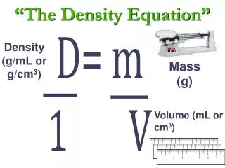
DensityDistance • SID – Inverse Square Law • Intensity of radiation is inversely proportional to the square of the distance from the source • Increase SID, decrease Density I1 D 22 ______ = ______ I 2 D 1 2
Density MaintenanceFormula mAs1 D12 _____ = _____ mAs2 D22
Density • Filtration • Increase in added filtration decreases density
DensityBeam Restriction • Reduction of beam size reduces the production of scattered radiation, therefore reducing the amount of radiation reaching the film and reducing density. • Dependent upon: • Amount of scatter produced • Efficiency of grid • Amount of reduction
DensityBeam Restriction • Usually not necessary to compensate for a restriction in beam size because the change in density is less than 30% and therefore not noticeable. Compensation may be required: Large patient High Kilovoltage technique low grid efficiency (or no grid)
DensityAnatomical Part • Greater tissue thickness, the less density. • Radiopaque contrast media decreases density. • Radiolucent contrast media increases density. • Destructive pathology increases density. • Additive pathology decreases density. • Angled techniques decrease density • Variable (depends on degree of angulation)
DensityAnatomical Part • Angled techniques decrease density • Variable (depends on degree of angulation)
DensityGrids • Grids absorb scattered radiation, therefore decreasing density. • Loss of density compensated for by increasing mAs. • Primary purpose of grid is to increase contrast
DensityGrids • Grid Conversions • No grid to: GFC • 5:1 2 MAS1 GCF1 • 6:1 3 -------- = ------- • 8:1 4 MAS2 GCF2 • 12:1 5 • 16:1 6
DensityFilm/Screen Combination • As intensifying screen speed increases, density increases; to compensate mAs is decreased. MAS1 RS2 ----------- = ----------- MAS2 RS1 MAS2
Density • Film Processing should not affect density as long as processing parameters are maintained.
Density Increase mAs + Decrease mAs - Increase kVp + Decrease kVp - Increase generator + Decrease generator – Focal Spot Size 0 Anode Heel Effect 0 Increase SID - Decrease SID + Increase filtration - Decrease filtration + Inc. Beam restrict - Dec beam restrict + Inc. part thickness - Dec. part thickness -
Density Radiolucent CM + Radiopaque CM - Additive pathology - Destructive pathology + Increase grid ratio - Decrease grid ratio + Increase F/S RS + Decrease F/S RD - Increase Processing + Decrease Processing - Increase CR angle - Decrease CR angle +