Download
1 / 16
160 likes | 296 Vues
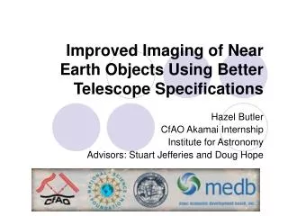
This project focuses on improving the imaging of Near Earth Objects (NEOs), such as asteroids and space debris, by addressing telescope limitations like diffraction limits and atmospheric distortion. By employing adaptive optics and image restoration through multi-frame blind deconvolution, we can enhance resolution and track orbital paths more effectively. Simulations based on varying pupil sizes and analyzing intensity differences help in refining the imaging process, ultimately aiding in monitoring satellite health and predicting NEO trajectories.

E N D
Improved Imaging of Near Earth Objects Using Better Telescope Specifications Hazel Butler CfAO Akamai Internship Institute for Astronomy Advisors: Stuart Jefferies and Doug Hope
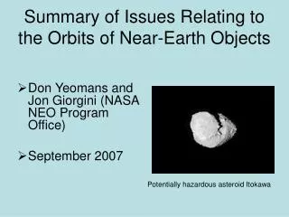
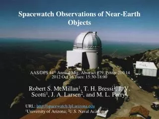
Motivation • Imaging of Near Earth Objects (NEO) • Asteroids, satellites, space debris • Monitor Satellite Health • Cost millions • Track orbits
Telescope Limitations • Diffraction Limit • Telescope Aperture • Resolution • Atmospheric Distortion • R0
Atmospheric Distortion Planer Light Waves Atmosphere Distorted Light Waves
Overcoming this Problem • Adaptive Optics • Image Restoration • Prior Information • Point Spread Function (PSF)
Uses multiple frames to estimate the PSF and the object Multi-Frame Blind Deconvolution
Telescope Pupil Function • Specify radius of the telescope pupil
My Project • Wrong pupil size • Intensity differences error Medium Intensity Low Intensity High Intensity object Point Spread Function
Methodology Build Pupil Program Build Error Program Run Simulations Build Intensity Difference Program Analyze Results Calculate Errors Calculate Errors Analyze Results Conclusions
Computing the Error ( ) 2 Truth Image Estimated Image 2 Truth Image
Simulation Parameters • The atmospheric distortion (D/r0) was 5. • Intensity Levels • High Threshold (0.05) • Low Threshold (0.005) • 3 Pupil Radii • 16 Frames
Conclusions • Pupil Radius Significance • High and Low Intensity • Image Improvement • Odd Phase Results
References and Sources • Astronomy Picture of the Day images http://antwrp.gsfc.nasa.gov/apod/astropix.html • Bracewell, R. The Fourier Transform and its Applications. 2000. McGraw-Hill Higher Education, Boston • Nocedal, J. and Wright, S. Numerical Optimization. 1999. Springer-Verlag New York, Inc., New York • Roggemann, M and Welsh, B. Imaging through turbulance. 1996 CRC press LLC, Boca Raton
Acknowledgements • Institute for Astronomy • Doug Hope • Stuart Jefferies • Cindy Geibink • Center for Adaptive Optics • Malika Bell • Lisa Hunter • Hilary O’Bryan • Maui Economic Development Board • Isla Yap • Maui Community College • Mark Hoffman • Funding provided through the Center for Adaptive Optics, a National Science Foundation Science and Technology Center (STC), AST-987683