Imaging of diffraction objects using post-stack reverse-time migration
Imaging of diffraction objects using post-stack reverse-time migration. I. Silvestrov* (OPERA, IPGG SB RAS), R. Baina (OPERA) and E. Landa (OPERA). Outline. Motivation Description of the proposed algorithm Synthetic example based on Sigsbee model Real-data example.

Imaging of diffraction objects using post-stack reverse-time migration
E N D
Presentation Transcript
Imaging of diffraction objects using post-stack reverse-time migration I. Silvestrov* (OPERA, IPGG SB RAS), R. Baina (OPERA) and E. Landa (OPERA)
Outline • Motivation • Description of the proposed algorithm • Synthetic example based on Sigsbee model • Real-data example
Diffraction imaging algorithm in dip-angle domain Landa, E., Fomel S., and Reshef M. 2008. Separation, imaging, and velocity analysis of seismic diffractions using migrated dip-angle gathers. 78th Annual International Meeting, SEG, Expanded Abstracts, 2176–2180 Diffractions and reflections have different shapes in migrated dip-angle domain
Motivation • Diffraction imaging in areas where Kirchhoff migration fails (e.g. subsalt) • Numerical efficiency of the diffraction imaging algorithm Our choice: Post-stack Reverse-time migration (RTM)
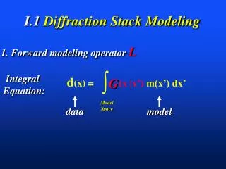
Post-stack reverse-time migration For given data d(x; t) we solve wave-equation with half-velocity V/2 in reverse-time: (1) Image is simply the wavefield at zero time: Why we can not use previous approach for diffraction separation? • Due to summation over receivers in (1) we do not have extra dimension for straightforward construction of CIGs • Analyzing the wavefield at zero time is equivalent to analyzing the image itself. However, we want to analyze the data and not the image.
Common image gathers in surface dip-angle domain As an extra dimension in CIGs we propose to use dip of event in data domain (horizontal slowness): Zero-offset data Plane-wave components of ZO data Model
Common image gathers in surface dip-angle domain 2 1 1 2 p p p=-0.0012 s/m p=0.0012 s/m p=0 CIGs with respect to “surface” dip Migration of plane-wave data components Reflection is a focused event. Diffraction is a horizontal line at the correct diffraction position. How to separate them?
Diffraction separation using Kurtosis measure Inverse Kurtosis measure: Kurtosis is a measure of peakedness of a probability distribution. Inverse Kurtosis is low for focused events. At the same time inverse Kurtosis is large for coherent events as a correlation of a squared signal with a constant. The events above a predefined threshold level are considered as diffractions
Plane-wave decomposition using sparse local Radon transform Local Radon transform is defined as: And its adjoint as: To find the model we use greedy approach to minimize the least-squares misfit: The plane-wave data section is obtained by summation over all local windows: Wang, J., Ng, M., and Perz, M. 2010. Seismic data interpolation by greedy local Radon transform. Geophysics 75(6), WB225-WB234. Giboli, M., Baina, R., and Landa, E., 2013. Depth migration in the offset-aperture domain: Optimal summation. SEG Technical Program Expanded Abstracts, 3866-3871
The proposed algorithm for diffraction separation based on post-stack RTM • Plane-wave decomposition of zero-offset stack • Sparse local Radon transform based on greedy approach • Depth migration of each plane-wave seismogram • RTM with zero-time imaging condition • Resorting of images into CIGs with respect to dip in data domain • Diffraction/reflection separation based on defocusing criteria • Sparse local Radon transform based on greedy approach • Inverse kurtosis as a measure of defocusing
Sigsbee model (post-stack RTM result) Simple part Complex part Two parts of the model will be considered in diffraction imaging
Plane-wave data component of zero-offset section Horizontal slowness p=-0.00014 s/m
Plane-wave data component of zero-offset section Horizontal slowness p=0
Common image gathers in simple part X=6000 X=6000 Before separation After separation
Diffraction separation result in simple part Before separation After separation
Diffraction separation result in complex part CIG at 15200m before and after separation After separation Before separation After separation
Snapshots for diffraction and reflection below salt body Reflection Diffraction Exploding reflector modeling
Snapshots for diffraction and reflection below salt body Reflection Diffraction Exploding reflector modeling
Snapshots for diffraction and reflection below salt body Diffraction’s and reflection’s responses are similar at the surface Diffraction Reflection Redatuming level Redatuming may be used to simplify the wavefield Reshef M., Lipzer N., Dafni R. and Landa E., 3D post-stack interval velocity analysis with effective use of datuming, Geophysical Prospecting 1(60), 18–28, January 2012
Diffraction separation result in complex part Diffraction image for redatumed data Diffraction image for initial data Initial image
CIGs before and after redatuming X=15200 Before redatuming After redatuming
Real-data example. Oseberg oil field in the North Sea. Zero-offset stack obtained using path-integral summation approach
Conclusion • We propose a method for imaging small scale diffraction objects based on post-stack Reverse-time migration • The method is based on separation between specular reflection and diffraction components of the total wavefield in the migrated domain. We used continuity of diffractions in the surface dip-angle CIGs as a criterion for separating reflections from diffractions • Synthetic and real data examples illustrate efficient application of the method
Acknowledgements The authors thank TOTAL for supporting this research. OPERA is a private organization funded by TOTAL and supported by Pau University whose main objective is to carry out applied research in petroleum geophysics.