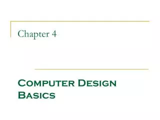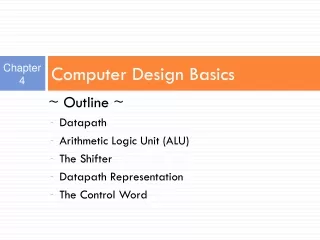
Understanding Computer Architecture: Basics and Microoperations in Datapath Design
This resource provides a comprehensive introduction to computer architecture, detailing key specifications such as Instruction Set Architecture (ISA) and microoperation implementation in datapaths. Explore the components of a simple computer architecture, including the datapath, control unit, registers, Arithmetic Logic Unit (ALU), and shifters. Through practical examples and simulations, gain insights into how microoperations are executed and the role of control words in data handling and processing. Ideal for students and professionals looking to deepen their understanding of computer design basics.

Understanding Computer Architecture: Basics and Microoperations in Datapath Design
E N D
Presentation Transcript
Introduction • Computer Specification • Instruction Set Architecture (ISA) - the specification of a computer's appearance to a programmer at its lowest level • Computer Architecture - a high-level description of the hardware implementing the computer derived from the ISA • The architecture usually includes additional specifications such as speed, cost, and reliability.
SimpleComputerArchitecture • Simple computer architecture decomposed into: • Datapath for performing operations • Control unit for controlling datapath operations • A datapath is specified by: • A set of registers • The microoperations performed on the data stored in the registers • A control interface
Datapaths • The set of registers • A set of registers with common access resources called a register file • Microoperationimplementation • Buses- shared transfer paths • Arithmetic-Logic Unit (ALU) - shared resource for implementing arithmetic and logicmicrooperations • Shifter - shared resource for implementing shiftmicrooperations
Datapath Example • Four parallel-loadregisters • Two mux-based register selectors • Register destinationdecoder • Mux B for external constant input • Buses A and B with externaladdress and data outputs • ALU and ShifterwithMuxF for output select • Mux D for external data input • Logic for generating status bitsV, C, N, Z
Apply 01 to A select to place contents of R1 onto Bus A • Apply 10 to B select to place contents of R2 onto B data and apply 0 to MB select to place B data on Bus B • Apply 0010 to G select to perform addition G = Bus A + Bus B • Apply 0 to MF select and 0 to MDselect to place the value of G onto BUS D • Apply 00 to Destination select to enable the Load input to R0 • Apply 1 to Load Enable to force the Load input to R0 to 1 so that R0 is loaded on the clock pulse (not shown) • The overall microoperation requires1 clock cycle Datapath Example: Performing a Microoperation • Microoperation: R0 ← R1 + R2
Arithmetic Logic Unit (ALU) • Decompose the ALU into: • An arithmetic circuit • A logic circuit • A selector to pick between the two circuits
TheShifter 4-Bit BasicShifter
DatapathWithFunction Unit Select Codes Select, Select, and G H MF in T of Codes FS
The Control Word • The datapath has many control inputs • The signals driving these inputs can be defined and organized into a control word • To execute a microinstruction, we apply control word values for a clock cycle. • For most microoperations, the positive edge of the clock cycle is needed to perform the register load
n D data R W 0 Write 15 D A 14 D address 13 8 n x Register file 12 9 A address B address AA BA 11 8 7 10 A data B data n n n Constant in 1 0 6 MB MUX B Bus A n Address out Bus B n Data out A B V 5 Function C 4 FS unit N 3 Z 2 n n Data in 0 1 MD 1 MUX D Bus D Control Word
n D data R W 0 Write 15 D A 14 D address 13 8 n x Register file 12 9 A address B address AA BA 11 8 7 10 A data B data n n n Constant in 1 0 6 MB MUX B Bus A n Address out Bus B n Data out A B V 5 Function C 4 FS unit N 3 Z 2 n n Data in 0 1 MD 1 MUX D Bus D
n D data R W 0 Write 15 D A 14 D address 13 8 n x Register file 12 9 A address B address AA BA 11 8 7 10 A data B data n n n Constant in 1 0 6 MB MUX B Bus A n Address out Bus B n Data out A B V 5 Function C 4 FS unit N 3 Z 2 n n Data in 0 1 MD 1 MUX D Bus D Datapath Simulation