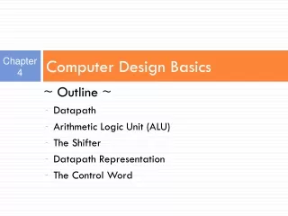
Chapter 4 Computer Design Basics
Chapter 4 Computer Design Basics. Chapter Overview. Part 1 – Datapaths Introduction Datapath Example Arithmetic Logic Unit (ALU) Shifter Datapath Representation Control Word Part 2 – A Simple Computer Instruction Set Architecture (ISA) Single-Cycle Hardwired Control Instruction Decoder

Chapter 4 Computer Design Basics
E N D
Presentation Transcript
Chapter Overview • Part 1 – Datapaths • Introduction • Datapath Example • Arithmetic Logic Unit (ALU) • Shifter • Datapath Representation • Control Word • Part 2 – A Simple Computer • Instruction Set Architecture (ISA) • Single-Cycle Hardwired Control • Instruction Decoder • Sample Instructions • Single Cycle Computer Issues • Multiple Cycle Hardwired Control • Sequential Control Design Digital 2 will focus on Part 1 Part 2 will be covered in Computer Architecture & Microprocessor. however prior reading is encourage.
Part 1 : Datapath • Computer Specification • Instruction Set Architecture (ISA) • The specification of a computer's appearance to a programmer at its lowest level. • It describe all the available instruction set in the computer, where it is kept (address) and how to use it (read). • Computer Architecture • A high-level description of the hardware implementing the computer derived from the ISA • Consists of: A Datapath and A Control
Part 1 : Datapath • The architecture usually includes additional specifications such as speed, cost, and reliability. • Simple computer architecture comprise of: • Datapath for performing operations • Control unit for controlling datapath operations • A datapath is specified by: • A set of registers • The microoperations performed on the data stored in the registers • A control interface
Datapath and Control • Control Unit - Determines the enabling and sequencing of the operations • Datapath - performs data transfer and processing operations The control unit receives: – External control inputs – Status signals The control unit sends: – Control signals – Control outputs
A General Purpose Processor CPU Control Word
Computer Datapath • Implements register transfer microoperations and serves as a framework for the design of detailed processing logic. • Control Word • Provides a tie between the datapath and the control unit.
Datapaths : Guiding principles for basic datapaths (Typical): • The set of registers • Collection of individual registers • A set of registers with common access resources called a register file • A combination (individual & set of reg.) of the above • Microoperation implementation • One or more shared resources for implementing microoperations • Buses - shared transfer paths • Arithmetic-Logic Unit (ALU)- shared resource for implementing arithmetic and logic microoperations • Shifter - shared resource for implementing shift microoperations
Datapath • The combination of: • A set of registers with a shared ALU, and interconnecting paths.
Block Diagram of a Generic Datapath • Four parallel-load registers • • Two mux-based register selectors • • Register destination decoder • • Mux B for external constant input • • Buses A and B with external address and data outputs • • ALU and Shifter with Mux F for output select (Function Unit) • • Mux D for external data input • • Logic for generating status bits V, C, N, Z
Block Diagram of a Generic Datapath Example: R1 R2 + R3 Note : G Select must refer to Function Table of Arithmetic Circuit (refer next 3 slides)
Arithmetic Logic Unit (ALU) • ALU Comprise of: • An arithmetic circuit (add, subtract) • A logic circuit (bitwise operation) • A selector to pick between the two circuits 1 2 3
Arithmetic Logic Unit (ALU) • ALU Comprise of: • An arithmetic circuit • An n-bit parallel adder • A block of input logic with 2 selectors S1 and S0 1 * Mode Select (S2) distinguishes between arithmetic and logic operations which actually construct item 3 G Select (4-bits)
ALU • Is a combinational circuit that performs a set of basic microoperations on: • Arithmetic, and • Logic • Has a number of selection lines used to determine the operations to be performed e.g. • n selection lines can specify up to 2n types of operations.
An n-bit ALU • n data inputs of A are combined with n data inputs of B, to generate the result of an operation at the G outputs. • S2=0 Arithmetic operations (8). Which one – is specified by S1, So and Cin. • S2=1 Logic operations (4). Which one – specified by So and Cin.
Question • What are the 8 arithmetic operations? • What are the 4 logic operations? Table 10-1 Figure 10-6
How to design the ALU? • Design the arithmetic section • Design the logic section • Combine both sections
To be designed… One Stage of ALU S2 = 0 for Arithmetic S2 = 1 for Logic
Arithmetic Circuit Design Given …
Arithmetic Circuit Design 1 Analyse the Circuit: Use Note : X = A G = A + Y + Cin For S1 and S0 = 00, then G = A + 0 + 0 G = A Eg. We can verify for n = 4 bit: A = 1010 B = 0101
Y = BS0 + BS1 Building the B input Logic • Obtain the K-Map • Get the Boolean Expression Input = S1, S0 and B Output = Y
Y Y = BS0 + BS1 Building the B input Logic Example of a 4-bit Arithmetic Circuit Any other alternative?
Use Multiplexer 0 B B 1
Building the Logic Circuit 2 • The Logic Circuit performs bitwise operation • Commonly : AND, OR, XOR and NOT Note : if 4 bit is wanted, then we have to arrange it in array One Stage of Logic Circuit
Building the Selector for choosing Arithmetic or Logic Unit 3 S2 = 0 for Arithmetic S2 = 1 for Logic One Stage of ALU Refer also Fig. 10.2
Exercise • Design a 4-bit logic unit of an ALU to do:
Exercise • Draw the complete diagram of the ALU, which consists of: • The Arithmetic Circuit • The Logic Circuit • The Selector circuit For: • A bit-slice (one stage) circuit • A 2-bits circuit • A 4-bits circuit
Example: R1 R2 + R3 Therefore; S2 = 0 for Arithmetic operation S1 = 0 S0 = 1 Cin = 0 LSB G Select (4-bits) 0010 0010 Answer : MSB
The Shifter • The Shifter Shifts the value on Bus B, placing the result on an input of MUX F • The Shifter can: • Shift Right • Shift Left • It is obvious that the shifter would be a bidirectional shift register with parallel load. • Alternatively, a combinational logic shifter can be constructed using multiplexers.
Barrel Shifter • Barrel in BM = ? • “Tong Deram” • Is a combinational circuit. • Can shift data more than 1-bit position in a single clock cycle. • No. of bit positions to be shifted or rotated is specified by the “select” inputs. • Shift here is Rotate Left. • Data is shifted left with the MSB rotated back as LSB.
4 Bit Basic Shifter • Serial Inputs: • IR for right shift • IL for left shift
Barrel Shifter • The data can be shifted or rotated more than one bit position in a single clock cycle • By using MUX. • 2n input requires 2n MUX.
4-Bit Barrel Shifter • A rotate is a shift in which the bits shifted out are inserted into the positions vacated • The circuit rotates its contents left from 0 to 3 positions depending on Selector S. Note that a left rotation by three (3) positions is the same as a right rotation by one position in this 4 bit barrel shifter
Exercise Find the output Y for each of the following bit patterns applied to S1, S0, D3, D2, D1 and D0: • 000101 • 101010 • 010011
Datapath Representation Regs, mux, dec., enable hw Register File One hierarchy level Up ALU, shifter, mux F, zero detect Function Unit
n D data Write m D address m 2 n x Register file m m A address B address A data B data Constant in n n n 1 0 MB select MUX B n Bus A Address out Bus B n Data out A B 4 FS V Function C unit N Z F n n Data in 0 1 MD select MUX D Datapath Representation (continued) • In the register file: • Multiplexer select inputs become A address and B address • Decoder input becomes D address • Multiplexer outputs become A data and B data • Input data to the registers becomes D data • Load enable becomes write • The register file now appears like a memory based on clocked flip-flops (the clock is not shown) • The function unit labeling is quite straightforward except for FS
Definition of Function Unit Select (FS) Codes • Notice that the G, H and MF Select are combined as FS. • Boolean Equations: • MF = F3.F2 • Gi = Fi • Hi = Fi
Control Word • The datapath has many control inputs. • The signals driving these inputs can be defined and organized into a control word. • To execute a microinstruction, we apply control word values for a clock cycle. • For most microoperations, the positive edge of the clock cycle is needed to perform the register load. • The datapath control word format and the field definitions are shown on the next slide.
The Control Word • Represents the control inputs to the datapath. • Determines the microoperation to be executed for each clock pulse.
A Datapath with Control variables Mux B Selects between constant values on Constant in and register values on B data. • Register File • 8 registers, R0 to R7. • Outputs to Function Unit via Bus A and Bus B. Mux D Selects the function unit output or the data on Data in as input for the register file. • 16 control inputs (represented by control word).
The Control Word Fields Control Word Fields (7): • DA – D Address • AA – A Address • BA – B Address • MB –Mux B • FS – Function Select • MD –Mux D • RW – Register Write • The connections to datapath are shown in the next slide Total : 16-bits (4-bits) (3-bits) (3-bits) (3-bits) (1-bit) Register Fields
How a Control Word Specifies a Microop DA (3-bits): Select 1 of 8 destination registers for the result of the microop. AA (3 bits): Select 1 of 8 source registers for the Bus A input. BA (3-bits): Selects a source register for the 0 input of the Mux B. MB (1-bit): Determines whether Bus B carries the contents of the selected source register or a constant value. FS (4-bits): Contains 1 of 15 microop codes, i.e. the operation of the Function Unit. MD (1-bit): Selects the function unit output or the data on Data in as the input to Bus D. RW (1-bit): Determines whether a register is to be written or not.
Control Word Encoding Table 10-5
R1 R2 + R3 + 1 How RTL is coded as a Control Word • R2: source register for A input of ALU • R3: source register for B input of ALU • Function Unit operation: F= A+B+1 • R1: Destination register for results • DA AA BA MB FS MD RW • R1 R2 R3 Register F= A+B+1 Function Write 001 010 011 0 0101 0 1
R4 sl R6 How RTL is coded as a Control Word • Shifter : to shift left • Contents of R6, shifted to the left, is transferred to R4 • Shifter is driven by B bus • Source`register: specified in BA field. • DA AA BA MB FS MD RW • R4 - R3 Register F= sl B Function Write 100 XXX 110 0 1110 0 1
R1 R2 R3 Reg F=A+B+1 Function Write R1 R2 + R3 + 1 Answer : Example 1 0010100110010101 Given the 16-bit Control Word as Field : DA AA BA MB FS MD RW Binary : Symbolic : 001 010 011 0 0101 0 1 Refer to Control Word Encoding Table
R4 sl R6 Answer : Example 2 1000101100111001 Given the 16-bit Control Word as Field : DA AA BA MB FS MD RW Binary : Symbolic : 100 010 110 0 1110 0 1 R4 R2 R6 Reg F=sl B Function Write Refer to Control Word Encoding Table
Data Out R3 Answer : Example 3 0100000110011000 Given the 16-bit Control Word as Field : DA AA BA MB FS MD RW Binary : Symbolic : 010 000 011 0 0110 0 0 R2 R0 R3 Reg F = A-1 Data_In No_Write Refer to Control Word Encoding Table Address B is selected because MB = 0 (Refer to block Diagram on Slide 7)
R4 Data In Answer : Example 4 1000000110011011 Given the 16-bit Control Word as R4 R0 R3 Reg F = A-1 Data_In Write Field : DA AA BA MB FS MD RW Binary : Symbolic : 100 000 011 0 0110 1 1 Refer to Control Word Encoding Table Address D is selected because MD = 1 (Refer to block Diagram on Slide 7)