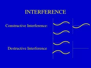
Evaluating Interference Effects on Radar Receivers and Criteria for Effective Spectrum Sharing
140 likes | 288 Vues
This paper presented at the IEEE Electromagnetic Compatibility Conference discusses the impact of interference from communication systems on radar receivers. As proposals for sharing radar frequency bands have increased, it has become essential to determine the thresholds at which interference degrades radar performance. The National Telecommunications and Information Administration (NTIA) and the Institute for Telecommunication Sciences have been researching these thresholds since 2002. The paper outlines measurement procedures and presents key findings related to probability of detection (Pd) under various levels of interference.

Evaluating Interference Effects on Radar Receivers and Criteria for Effective Spectrum Sharing
E N D
Presentation Transcript
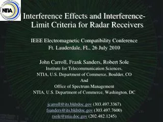
Interference Effects and Interference-Limit Criteria for Radar Receivers IEEE Electromagnetic Compatibility Conference Ft. Lauderdale, FL, 26 July 2010 John Carroll, Frank Sanders, Robert Sole Institute for Telecommunication Sciences, NTIA, U.S. Department of Commerce, Boulder, CO And Office of Spectrum Management NTIA, U.S. Department of Commerce, Washington, DC jcarroll@its.bldrdoc.gov (303.497.3367) fsanders@its.bldrdoc.gov (303.497.7600) rsole@ntia.doc.gov (202.482.1245)
NTIA Involvement Radar systems have historically been allocated in bands where they do not share with communication systems. But in recent years proposals have been made for communication systems to operate in radar bands. These include: Radio local area networks (RLANS); Satellite Signals; Various new mobile radio systems including WiMax; These proposals have raised the question: At what thresholds do various types of radio interference degrade the performance of radar receivers? Institute for Telecommunication Sciences – Boulder, Colorado
NTIA Involvement Sharing proposals may directly affect US Government radar systems. Therefore it is critical that technical parameters for sharing between radar receivers and non-radar systems be accurately quantified. PROBLEM: Lack of quantitative data regarding thresholds at which various types of interference degrade performance of radar receiver systems. Starting in FY-2002, NTIA Office of Spectrum Management and NTIA Institute for telecommunication Sciences undertook a joint effort to determine thresholds for interference to radar receivers. Airport Surveillance Air-Search Radar Institute for Telecommunication Sciences – Boulder, Colorado
Radar Interference Criterion: I/N Communication receivers typically experience interference effects as a function of the ratio of the interference level to the level of the desired signal (S/I or C/I). Radar receivers, in contrast, normally operate against their internally generated noise. They are noise limited and thus the critical interference level parameter is the ratio I/N within the radar receiver IF stage. But what criteria should be used to determine radar receiver performance at a given I/N level? Fixed ground-based weather surveillance radar display in the presence of strong interference. Institute for Telecommunication Sciences – Boulder, Colorado
Radar Performance Criterion:Probability of Detection of Controlled Targets OSM and ITS decided to assess radar performance on the basis of probability of detection (Pd) of desired targets as a function of interference level (I/N) in the radar IF stage. Target levels would have to be controlled during measurements. Therefore the targets had to be generated and injected along with interference. Baseline Pd needed to be marginal: targets strong enough to be easily observed, but nevertheless at the edge of radar’s capability. Decision was made to set baseline Pd of desired targets at Pd = 90%. Then interference effects would be measured relative to that performance level. Air surveillance radar ppi display with internally generated targets Institute for Telecommunication Sciences – Boulder, Colorado
Radar Interference Measurement Procedure Although procedures have varied slightly from radar to radar, the essential procedure that NTIA (OSM and ITS) has used is: 1) Disconnect radar receiver and inject desired (controlled) targets at the RF stage so that they are handled the same way as regular returns. 2) Adjust target level until Pd is as close as possible to 90%. 3) Inject interference signals at the radar RF stage. For each interference modulation, start at I/N=-12 dB, and successively raise the level to: -12 dB, -10 dB, -9 dB, -6 dB, -3 dB, 0 dB, +3 dB, +6 dB, on up to as much as +60 dB if necessary. OSM engineer preparing a maritime radar for signal injection at Curtis Bay Coast Guard Station near Baltimore. 4) Count at least 200 desired targets to obtain Pd for each level of interference. Interference types tested include: CW; pulsed CW; CDMA; TDMA; BPSK; OFDM; and UWB; and a variety of simulated radar emissions. Not all modulations have been used on all radars. Institute for Telecommunication Sciences – Boulder, Colorado
Typical Radar Interference Testing Block Diagram Note: Some live-target tests have also been performed. Institute for Telecommunication Sciences – Boulder, Colorado
Typical Setup (DoD/FAA/DHS Radar) Institute for Telecommunication Sciences – Boulder, Colorado
Radars Types Measured (2002-2010) • Several maritime radars in S and X-bands (in both the US and the UK); • Two models of DoD/FAA/DHS long-range radars in L-band; • Airport surveillance radars in S-band. • Weather surveillance radars in S and C bands. • Airborne weather surveillance radar in X-band. • Airport surface detection radar in X-band; • Precision approach radar in X-band. • Wind profiler radar in UHF. Institute for Telecommunication Sciences – Boulder, Colorado
Example of Pd Data Curves Institute for Telecommunication Sciences – Boulder, Colorado
Target Losses at Low I/N Levels Target losses at low I/N levels are insidious because there are no ancillary effects to indicate that interference is occurring or that targets are being lost. Institute for Telecommunication Sciences – Boulder, Colorado
Summary of Results to Date • Interference at high duty cycles (above about 2%), such as from communication signals, typically causes target losses to begin at I/N levels between -10 to -6 dB.; • Interference at low duty cycles (less than 2%), such as from other radars, can often be sustained at I/N levels as high as +30 dB to +60 dB without degrading receiver performance. • Target losses due to low levels of interference are insidious because no visible effects are associated with the interference. The targets simply fade away. • Target losses can occur at any range. Losses do not just occur at the edge of radar coverage, but rather anywhere that the targets are close to radar receiver noise. Institute for Telecommunication Sciences – Boulder, Colorado
Summary of Results to Date (cont.) • Meteorological radars show effects at the lowest levels: Wind profilers show effects at I/N levels as low as -18 dB; • Interference thresholds go lower as the number of pulses used to integrate radar targets increases. • Target loss curves (Pdas a function of I/N) are analytically predictable based on the number of pulse echoes used to integrate targets. • ITU-R criteria of -6 dB I/N threshold for interference analyses are barely adequate for many radar types. Institute for Telecommunication Sciences – Boulder, Colorado
Further Reading:-----------------------------------------------Sanders, Sole, Bedford, Franc, and Pawlowitz: Effects of Interference on Radar Receivers, (NTIA Technical Report TR-06-444)Available:http://www.its.bldrdoc.gov/pub/ntia-rpt/06-444/ Institute for Telecommunication Sciences – Boulder, Colorado