Download
1 / 39
520 likes | 1.03k Vues
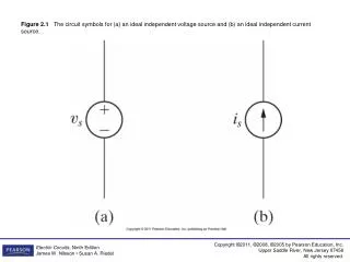
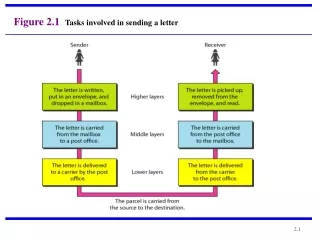
Figure 2.1 Tasks involved in sending a letter. 2-2 THE OSI MODEL.

E N D
2-2 THE OSI MODEL Established in 1947, the International Standards Organization (ISO) is a multinational body dedicated to worldwide agreement on international standards. An ISO standard that covers all aspects of network communications is the Open Systems Interconnection (OSI) model. It was first introduced in the late 1970s. Topics discussed in this section: Layered ArchitecturePeer-to-Peer Processes Encapsulation
Note ISO is the organization.OSI is the model.
2-3 LAYERS IN THE OSI MODEL In this section we briefly describe the functions of each layer in the OSI model. Topics discussed in this section: Physical LayerData Link Layer Network Layer Transport Layer Session Layer Presentation Layer Application Layer
Note The physical layer is responsible for movements of individual bits from one hop (node) to the next.
Type of transmission media • Data rate • Topology • Transmission mode • Synchronization of clock
Note The data link layer is responsible for moving frames from one hop (node) to the next.
Framing • Physical addressing • Flow control • Error control • Access control
Note The network layer is responsible for the delivery of individual packets from the source host to the destination host.
Logical addressing • Routing
Note The transport layer is responsible for the delivery of a message from one process to another.
Service-point addressing • Segmentation and reassembly • Connection control • Flow control • Error control
Figure 2.11 Reliable process-to-process delivery of a message
Note The session layer is responsible for dialog control and synchronization.
dialog control (turn to transmit) • Synchronization (introducing check point)
Note The presentation layer is responsible for translation, compression, and encryption.
Translation • Encryption • Compression
Note The application layer is responsible for providing services to the user.
File transfer, access, and management. • Mail services
2-4 TCP/IP PROTOCOL SUITE The layers in the TCP/IP protocol suite do not exactly match those in the OSI model. The original TCP/IP protocol suite was defined as having four layers: host-to-network, internet, transport, and application. However, when TCP/IP is compared to OSI, we can say that the TCP/IP protocol suite is made of five layers: physical, data link, network, transport, and application. Topics discussed in this section: Physical and Data Link LayersNetwork LayerTransport Layer Application Layer
2-5 ADDRESSING Four levels of addresses are used in an internet employing the TCP/IP protocols: physical, logical, port, and specific. Topics discussed in this section: Physical AddressesLogical AddressesPort AddressesSpecific Addresses
Comparison of the OSI and TCP/IP Reference Models • Functionality of the layers is roughly similar Concepts central to OSI model • Services : The service definition tells what the layer does, not how entities above it access it . It defines the layer's semantics. • Interfaces : tells the processes above it how to access it. It specifies what the parameters are and what results to expect • Protocols: the layer's own business.
Comparison of the OSI and TCP/IP Reference Models • OSI reference model was devised before the corresponding protocols were invented. This ordering means that the model was not biased toward one particular set of protocols • the protocols came first, and the model was really just a description of the existing protocols • Number of layers: the OSI model has seven layers and the TCP/IP has four layers. • The TCP/IP model has only one mode in the network layer (connectionless) but supports both modes in the transport layer,