Download
1 / 22
220 likes | 322 Vues
Explore the basics of continuum mechanics, studying stress and strain concepts. Learn about forces, stress tensors, Mohr diagrams, principal stresses, and more, with applications in geology and engineering. Dive into the world of strain and stress analysis!

E N D
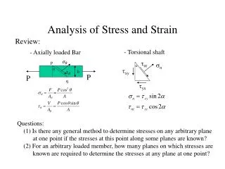
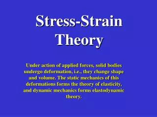
III. Strain and Stress • Basics of continuum mechanics, Strain • Basics of continuum mechanics, Stress Reading Suppe, Chapter 3 Twiss&Moores, chapter 15 Additional References : Jean Salençon, Handbook of continuum mechanics: general concepts, thermoelasticity, Springer, 2001 Chandrasekharaiah D.S., Debnath L. (1994) Continuum Mechanics Publisher: Academic press, Inc.
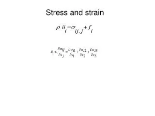
Force • Force is the cause of deformation and/or motion of a body. • 2 kinds of force: • Contact forces - involve physical contact between objects. Examples: the force involved in kicking a ball, pulling a wagon • Field forces - don't involve physical contact between objects. Examples: the gravitational force and the electromagnetic force
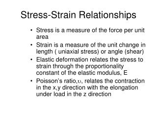
Stress Stress is force per unit area • Spreading out the weight reduces the stress with the same force. Normal Stress is skier’s weight distributed over skis surface area. F=mg
Sign convention for sn • Geomechanics: normal stress is positive in compression (convention used here) • Continuum mechanics:normal stress is positive in extension
The stress (red vector) acting on a plane at M is the force exterted by one side over the other side divided by plane area…
The stress tensor The state of stress at a point can be characterizes from the stress tensor defined as …
Stress acting on a plane at point M… Let n be the unit vector defining an oriented surface with elementary area da at point M. (n points from side A to side B) Let dT be the force exerted on the plane by the medium on side B. It can be decomposed into a normal and shear component parallel to the surface. The stress vector is: n Side B Side A Normal stress Shear stress
Principal stresses Because the matrix is symmetric, there is coordinate frame such that…. Engineering sign convention tension is positive,Geology sign convention compression is positive… Plane perpendicular toprincipal direction has no shear stress…
The deviatoric stress tensor… Stress tensor = mean stress + deviatoric stress tensor
The Mohr diagram 2-D stress on all possible internal planes… Sum of forces in 1- and 2-directions…
2-D stress on all possible internal planes… Sum of forces in 1- and 2-directions…
Rearrange equations… Rearrange equations yet again… Get more useful relationship betweenprincipal stresses andstress on any plane….
[1] What does a point on the circle mean? [2] What does the center of the circle tell you? [3] Where are the principle stresses? [4] What does the diameter or radius mean? [6] Where is the maximum shear stress? Any point on the circle gives coordinates acting on the plane at an angle qto 3 (, the mean or hydrostatic stress which produces change in volume is (2+3 In direction of and = 0; hence and are on the abscissa axis of Mohr graph (is the maximum possible shear stress= that which produces change in shape Maximum shear stress max occurs for =45°; then max = (
Representation of the stress state in 3-D using the Mohr cirles. This circle represent the state of stress on planes parallel to 2 The state of stress of a plane with any orientation plots in this domain t n 3 2 1 This circle represent the state of stress on planes parallel to 3 This circle represent the state of stress on planes parallel to 1
Classification of stress state <<0 0<< • General tension • General compression • Uniaxial Compression • Uniaxial tension • Biaxial stress =0 1=0 <0 0<
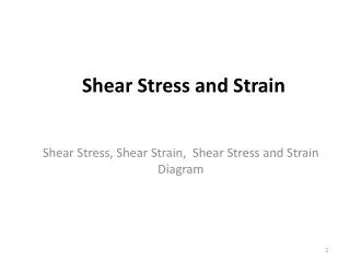
Pure Shear(as a state of stress) The exression ‘Pure shear’ is sometime used to characterize the a particular case of biaxial stress t =- 2=0 n Do not confuse with ‘pure shear’ as a state of strain
Pole of the Mohr circle t P A Dq 2Dq B n 3 1
Poles of the Mohr circle 1 t P A n 3 1
Applications • Dip angle of a normal fault • Dip angle of a thrust fault • Stress ‘refraction’ across an interface.
Poles of the Mohr circle 3 1 t P A n 3 1 A represent the state of stress on a facet with known orientation The geometric construction, based on the pole of the facet (P), allows to infer the state of stress on any orientation