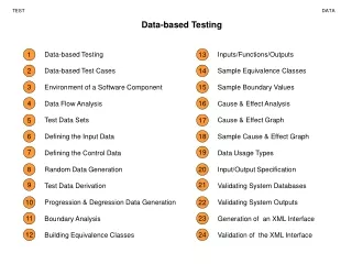
Compression Techniques for Efficient Test Data Reduction in Scan-Based Testing
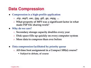
This presentation explores the issue of test data volume in scan-based testing of Integrated Circuits (ICs) post-manufacturing. It covers the necessary background, existing approaches, and proposes advanced techniques for reducing IC test data volume using compression. Key topics include digital testing basics, scan-based testing, solutions for test data volume problems, and Compression using codes. Solutions like Built-In-Self-Testing (BIST) and Test Resource Partitioning (TRP) are discussed along with compression code examples and LFSR reseeding approaches.

Compression Techniques for Efficient Test Data Reduction in Scan-Based Testing
E N D
Presentation Transcript
Test Data Compression for Scan-Based Testing Presented by Mustafa Imran Ali Research Assistant COE
Presentation Outline • Issue/Motivation • Necessary Background • Existing Approaches • Proposed Approach COE 599 Seminar Presentation
The Issue: Test Data Volume • Exhaustive IC chip testing after manufacture is critical to ensure product quality • Full Scan based IC testing using Automatic Test Equipment (ATE) the most widely used approach • test data volume IC complexity • A typical SoC ASIC may require 2.5 Gbits of test data • manufacturing costs test data volume • ATE memory capacity & test application time dictate cost “Hence the need for reducing IC test data volume” COE 599 Seminar Presentation
Digital Testing Basics open • Logical Modeling of Faults • Structural Faults Single Stuck-Fault Model • Faults List • Test Generation Process – determining test stimuli • Automatic Test Pattern/Vector Generation (CAD) • Fault Coverage Percentage stuck-at COE 599 Seminar Presentation
Continued… • Combinational vs. Sequential Circuits • Combinational Circuits • A fault detected by a single input vector • 100% fault coverage easy • Sequential Circuits • An ordered sequence of vectors required per fault • 100% faulty coverage hard! COE 599 Seminar Presentation
What is Scan-Based Testing? • Converts sequential circuit test generation problem into a combinational circuit test! • Guarantees 100% fault coverage • Internal flip-flop values (state) can be set and read (or ‘scanned in’ and ‘ scanned out’) • NO need for sequence of vectors to detect a fault! • Test vectors can be applied in any sequence • Each test vector is independent of others (allows reordering) COE 599 Seminar Presentation
How Does it Work? • Scan data is serially shifted in and out when device is in test mode Circuit Under Test (CUT) Primary Outputs Primary Inputs Test Mode Select Scan Data In Scan Data Out Clock COE 599 Seminar Presentation
Continued… COE 599 Seminar Presentation
Test data volume problem • Test data volume can be calculated as: Test data volume ≈ scan cells × scan patterns • Number of scan cells and scan patterns are related to complexity of designs • 10M gates, 1 scan cell/20 gates 0.5M scan cells • System-on-a-Chip designs require a large number of patterns to test each individual core e.g. up to 10,000 patterns • Multiple scan-chains: can reduce test application time but not test data volume • Pins limitations still limit maximum scan inputs feasible COE 599 Seminar Presentation
Both requirements growing rapidly test data storage, and test data bandwidth requirements between the tester and chip ATE capability cannot scale indefinitely for increasingly complex IC designs New testers with more memory, channels, and higher speed of operation not a good solution the cost of a high-speed tester will exceed $20 million by 2010 (ITRS Annual Report) ATE Limitations COE 599 Seminar Presentation
Solutions! • Eliminate the costly ATE! Use BIST • Built-in-Self-Testing generate test patterns on chip • Use Test Resource Partitioning (TRP) Solutions to ease burden on ATE • some hardware added on-chip, working in conjunction with external tester • helps reduce the test data and/or the test application time COE 599 Seminar Presentation
Built-In-Self-Testing (BIST) • Uses on-chip test pattern generation • Linear Feedback Shift Registers (LFSRs) • Limitations! Random Pattern Resistant Faults • Fault coverage is less than 100% • Very long test sequences required • Cores have to be BIST-ready • Solution: Mixed-mode BIST • Uses external testing + BIST • Lots of ongoing work in this area! COE 599 Seminar Presentation
TRP: Using on-chip decompression • Test sets contain a large number of don’t care values • Up to 98% bits can be don’t cares in industrial circuits • Approaches based on various compression encodings • Run-length encoding • Statistical coding • Golomb coding • Runlength + Huffman coding • Arithmetic coding • Dictionary based compression (LZ77, LZW) • Approaches based on LFSR seeding • LFSR used to generate scan chains • Different seeds values used for different test vectors COE 599 Seminar Presentation
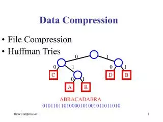
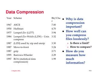
Compression using codes • Usually built on top of run-length encoding • Don’t care values are specified to maximize compression • Maximizing runs of ‘1’s and ‘0’s • Further compression achieved by encoding run values using variable length codes such as Huffman coding • Some schemes operate on set of difference vectors instead of original test set • Difference vector contain fewer 1s COE 599 Seminar Presentation
Compression Code Examples COE 599 Seminar Presentation
LFSR Reseeding based Approaches • LFSR is run in autonomous mode to fill scan chain with the test vector • LFSR seed is the starting state of an LFSR • Idea: compute a set of seeds that when expanded by LFSR will produce the test vectors • Different LFSR seeds will produce different test vectors COE 599 Seminar Presentation
The set of seeds are stored on the tester transferred to the LFSR one at a time seeds much smaller than the full test vectors LFSR size depends upon max. don’t cares/vector Continued… COE 599 Seminar Presentation
(Scan) Inputs Width Compression • Idea: driving multiple scan inputs with the same data values • only the common input data need to stored • Such inputs are grouped into a ‘compatible class’ • Different types of compatibility have been identified • Direct • Inverse • Combinational • Compression Ratio = #external chains / #internal chains COE 599 Seminar Presentation
Example: Using Direct Compatibility Test Vector 1 Test Vector 2 Test Vector 3 COE 599 Seminar Presentation
Continued… COE 599 Seminar Presentation
Logic (Combinational) Compatibility COE 599 Seminar Presentation
Example: Adding Logic Compatibility COE 599 Seminar Presentation
Proposed Scheme: Few Observations • Extent of compatibility depends on specified bits per scan vector • lesser the specified bits, the lesser the conflicts, resulting in greater compatibility • the longer the chains, the lesser the compatibility • Compatibility analysis per vector gives a lower bound on achievable reduction • Compatibility will increase as don’t care bits per vector increases COE 599 Seminar Presentation
Test Set Partitioning & Grouping • Partitioning the test set into acceptable & bottleneck vectors • A desired compression threshold set • Vectors satisfying the threshold called acceptable • Acceptable vectors grouped such that any group still satisfies the threshold • best case 1 group only • Bottleneck vectors relaxed to increase don’t cares COE 599 Seminar Presentation
Relaxation based on Decomposition • Each scan vector can be decomposed into multiple vectors • each having greater unspecified bits than the original vector • each vector now detects lesser faults than the original more specified vector. • bottleneck vectors are de-composed until the resulting vectors satisfy the threshold • vector that cover faults already covered by other vectors (redundant) is dropped • relaxed vectors are then made members of existing partition (s) COE 599 Seminar Presentation
An Example: 50% compression COE 599 Seminar Presentation
Continued… COE 599 Seminar Presentation
Decoder Hardware • Consists of MUXs to handle different partitions • #MUXs required depends upon #partitions created to satisfy the given compression requirement • Thus minimizing partitions minimizes the area overhead COE 599 Seminar Presentation
Partitioning Results • Each Test Set is configured into 64 internal scan chains and 75% compression targetted COE 599 Seminar Presentation
Conclusion • The proposed scheme aims to target user specified compression ratios • With an associated partitioning arrangement • H/W cost associated with extent of partitioning • Benefits of partitioning have been demonstrated on actual test sets • Decomposition-based test vector relaxation will (hopefully) lead to user specified compression ratios • Under implementation COE 599 Seminar Presentation