Download
1 / 37
420 likes | 725 Vues
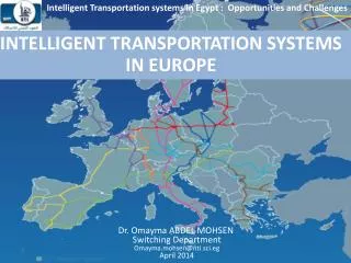
Intelligent Transportation systems in Egypt : Opportunities and Challenges. INTELLIGENT TRANSPORTATION SYSTEMS IN EUROPE. Dr. Omayma ABDEL MOHSEN Switching Department Omayma.mohsen@nti.sci.eg April 2014. The European Commission’s Directorate- General for Mobility and Transport (MOVE).

E N D
Intelligent Transportation systems in Egypt : Opportunities and Challenges INTELLIGENT TRANSPORTATION SYSTEMS IN EUROPE • Dr. Omayma ABDEL MOHSEN • Switching Department • Omayma.mohsen@nti.sci.eg • April 2014
The European Commission’s Directorate- General for Mobility and Transport (MOVE) • The European Commission(one of the main institutions of the European Union) is divided into several departments and services. The departments are known as Directorates-General (DGs). Each DG is classified according to the policy it deals with. • The European Commission’s Directorate-General for Mobility and Transport promotes a mobility that is efficient, safe, secure and environmentally friendly.
Mission of the Directorate-General for Mobility and Transport “The European Commission’s Directorate-General for Mobility and Transport is in charge of developing transport policies for the European Union. Its remit is to ensure mobility in a single European transport Area, integrating citizen’s needs, environmental policy, and competitiveness.”
THE EU AND TRANSPORT The 1992 Maastricht Treaty took a big step forward by introducing the concept of the Trans-European Transport Network (TEN-T). This strengthened the basis for Member States to act together to provide key links in the European transport infrastructure, on which the European single market depends TRANS-EUROPEAN TRANSPORT NETWORK (TEN-T CORE NETWORK CORRIDORS)
EUROPE AND ITS In the late 1980sthe EC began to invest in research in ITS for roads (the PROMETHEUS and DRIVEProgrammes, European ATIS Projects/Systems) Starting in the 1990sthe Euro-Regional Projects funded from the Trans- European Transport Network (TEN-T) budget made significant advances in harmonised data exchange (DATEX)between European road authorities and in the use of language independent traffic messages over the Radio Data System Traffic Message Channel (RDS-TMC). These Euro-Regional projects merged in 2007 into a single DG-MOVE project EasyWay
EasyWay http://www.easyway-its.eu/activities/
EasyWay-ITS http://www.easyway-its.eu/activities/
The European ITS Directive and action plan Two decades on from the pioneering DRIVE research programme, the EC tabled proposals designed to provide a framework for ITS applications and services connected with road transport, including their interfaces with other transport modes. The aim is to harmonise deployment and operational use of ITS throughout Europe where possible. The Commission’s proposals were subject to a long process of scrutiny before finally being adopted in 2010. The so-called ‘ITS Directive’ has a seven year lifespan during which time the EC is required to develop specifications for ITS systems and services in four priority areas
Policy framework for the deployment of ITS in Europe Action Plan for the Deployment of Intelligent Transport Systems (ITS) in Europe (2008) Directive2010/40/EU: Framework for the Coordinated and Effective Deployment and Use of Intelligent Transport Systems
ITS Action Plan The European Commission’s ITS Action Plan is working to accelerate and coordinate the deployment of ITS in road transport, including interfaces with other transport modes. The action plan was adopted after much preparatory work and a long consultation with stakeholders. Its main focus is to ensure the compatibility and interoperability of systems, to facilitate the continuity of ITS services, and to do so through coordinated and concerted action at EU level.
ITS Action Plan Road Safetyand Security Continuity ofTraffic & Freight Management IntegrationVehicle & Transport Infrastructure Data Protection & Liability European ITS Coordination Area 1 Legal framework for EU ITS cooperation Area 2 Area 4 Area 5 Area 6 EU-wide real time travel information Collection & provision of road data Accurate public data for digital maps Free minimum information service Optimal Use Road, Traffic & Travel Data Promotion of multi-modal journey planners Continuity of ITS services Services for freight transport & logistics Interoperability of electronic toll systems Promotion of in-vehicle safety systems Introduction of Europe-wide eCall Regulatory Framework on HMI Impact on Vulnerable road users Guidelines: Secure parking places for trucks Development& evaluation coop. systems Area 3 Specifications for I2I, V2X communication Collaboration platform on urban ITS Open in-vehicle Platform architecture Mandate for European standardisation Security & data protection Guidelines for public funding for ITS Decision support toolkit for ITS investments European ITS Framework architecture Liability, esp. in-vehicle safety systems 6 priority areas - 24 actions
ITS Action Plan Implementation The implementation of the ITS Action Plan represents a joint effort by several European Commission services, coordinated by the Directorate-General for Mobility and Transport with the direct and active collaboration of four other directorates general (DGs) of the Commission: • the Information Society and Media DG, • the Research and Innovation DG, • the Enterprise and Industry DG and • the Climate Action DG. The plan is also implemented in close cooperation with ITS stakeholders, as seen for example in the staging of various workshops on action plan topics.
Framework for the Coordinated and Effective Deployment and Use of Intelligent Transport Systems in force since26 Aug 2010 Directive 2010/40/EU Objectives • Establishing a framework for coordinated and effective deployment and use of ITS • Setting common priorities • Development of specifications and standards focused on interoperability and continuity 14 |
ITS Directive Timeline 2017 Aug • National Reports • Delegation ends • Multi-modal travel information 2016 Aug • COM Report 2015 2014 Feb • COM Report on Delegation Aug • National Reports • Real-time information • Truck parking reservation • eCall • Free min traffic information • Truck parking information 2013 Aug • COM report 2012 Feb • First specsto be ready Aug • NationalITS Plans 2011 Feb • Trans-position Aug • National Reports 2010 Feb • Work Programme 27 Aug Directivein force Source: ITS Policy and Funding Instruments in Multi-annualFinanacial Framework 2014-2020, PawelStelmaszczyk Head of ITS Unit,EuropeanCommission – DG MOVE
e-Call (Mobility and Transport MOVE) Intelligent transport systems News (18/03/2014) Vice-President Kallas welcomes deal on 112 eCall • Commission Vice-President SiimKallas welcomed the agreement today between the European Parliament and the Council on establishing emergency call response centresfor the handling of 112 eCalls. The eCall system automatically dials 112-Europe's single emergency number - in the event of a serious accident. Link: http://ec.europa.eu/transport/themes/its/news/ecall-deal_en.htm
ITS FRAME Architecture Action Area 2.3 of the EU ITS Action Plan requires the use of ITS Architectures to support the European objectives of the Plan. The European ITS Framework Architecture, also known as the FRAME Architecture, provides a suitable basis for this task. The FRAME Architecture was produced by the EC funded project KAREN (1998-2000). It has been maintained and enhanced continuously since then with cooperative systems being added by the E-FRAME project (2008-11). E-FRAME is funded by the EC, FP7 IST Programme (IST:Information Society Technology) Clearly this architecture is a candidate for use by those who are implementing the ITS Action Plan.
ITS FRAME Architecture The FRAME Architecture is quite large. When originally produced by the KAREN project it was documented in paper form, resulting in several large documents that were not easy to navigate. As part of the work of the FRAME projects the Functional Viewpoint is now available in HTML format. This is known as the FRAME Browsing Tool and can be viewed using Internet Explorer. A copy can be downloaded from the FRAME website at: http://www.frame-online.net/.
ITS FRAME Architecture The FRAME Browsing Tool provides an interactive interface through which it is possible to move from one part of the FRAME Architecture to another and to follow through the relationships between all of the functional elements. It includes the diagrams shown in Figures that follows, plus Data Flow Diagrams for all the hierarchies in each of the Functional Areas. It also includes the descriptions of all of the elements in the functionality, i.e. Functions, Data Stores and Data Flows, the Terminator and Actor descriptions, plus the identity and description of each User Need.
ITS FRAME Architecture The User Needs are divided up according to the areas in which the Services operate. Hence there are User Needs for: • Traveller Journey Assistance, • Traffic Management, • Public Transport Operations, • Freight and Fleet Operations, • Advanced Driver Assistance Systems, • Safety and Emergency Facilities, • Support for Law Enforcement and • Electronic Payment
FRAME Architecture Context Diagram In order for the functionality in each of the Functional Areas to work, it needs to be able to collect data from the outside world and to provide either that data, or a processed version of it back to the outside world. This is done by specific dedicated parts of the functionality in each Functional Area. The links with the outside world that this functionality needs are illustrated by what is called the "Context Diagram" which is shown in Figure.
Terminator • A Terminator is the link between the System (or ITS) and the outside World. • It provides a definition of what the System expects the outside World to do, the data it is expected to provide, and the data to be provided to it by the System. • A Terminator may be a • human entity, • system, or a • physical entity from which data can be obtained such as the atmosphere, or road surface.
DFD0 the highest level of Data Flow Diagram(provide Traveller Journey Assistance)
The FRAME Selection Tool • The Browsing Tool is intended to provide a convenient way of navigating around the Framework Architecture and of viewing its contents. • When the Framework Architecture is to be used as the basis for creating a particular ITS Architecture then it is necessary to select some (or possibly all) of the contents of the Framework Architecture. • A Selection Tool has been created to facilitate the tasks that need to be done, and it can be downloaded from the FRAME web site.
The FRAME Selection Tool The FRAME Selection, which contains a data base with all the elements of the FRAME Architecture does not perform any selections automatically, but it does support the architecture team in its use of the methodology in the following ways. • The team selects those User Needs that reflect the Stakeholder Aspirations. •The tool will then guide the architecture team to those parts of the Functional Viewpoint that help to satisfy those User Needs. • Once a Functional Viewpoint is considered acceptable, it can be used as the basis for one or more Physical Viewpoints. • Once a Physical Viewpoint has been completed one of the reports available from the Selection Tool can be used to provide the starting point for an analysis of the Physical Data Flows. This leads to the creation of the Communications Viewpoint, which shows the characteristics of the links required between each of the sub-systems and modules, plus those with the Terminators.
European ITS standards organisations • CEN/CENELEC (European Committee for Standardisation/European Committee for Electro-technical Standardization – based in Brussels) The CEN Technical Committee TC 278 on Road Transport and Traffic Telematics (established in 1991) has most to do with ITS, including those elements that need technical harmonization for inter-modal operation with other means of transport. CEN/TC 278 cooperates with the ITS committee of the International Standards Organisation (ISO/TC 204). • ETSI (European Telecommunications Standards Institute) Because ITS service provision relies on communications, especially the more advanced services, this makes ITS an area of strategic relevance to ETSI and one where ETSI leadership is required. • United Nations ECE (Economic Commission for Europe) World Forum The UNECE’s main focus has been communication between vehicles and between vehicles and infrastructure. Technical specifications for autonomous emergency braking and lane departure warning systems are two examples.
Lessons Learned and Conclusions • An ITS FRAME Architecture is a common language and a tool to discuss state of the art system functionalities. • Collaboration between different entities; Industry, Research and Innovation, Climate and environmental and Information and communication to deploy ITS. • The staging of various workshops on ITS topics.
References • http://europa.eu/about-eu/eu-history/index_en.htm • http://ec.europa.eu/index_en.htm • http://ec.europa.eu/about/ds_en.htm • “Mission of the Directorate-General for Mobility and Transport”http://ec.europa.eu/dgs/transport/doc/2010_05_move_mission_statements.pdf • John Miles, Finella McKenzie and Keith Keen , “Intelligent Transport Systems (ITS) Practitioners’ Guide to EUROPE”, ITS United Kingdom, RTI Focus (UK) Ltd, January 2011Ankerbold International Ltd, www. Its-uk.org.uk. • http://ec.europa.eu/transport/themes/infrastructure/doc/ten-t-country-fiches/ten-t-corridor-map-2013.pdf • http://www.channelingreality.com/NAU/IVHS/Prometheus_Europe_fhwa.dot.pdf