Heat Exchangers
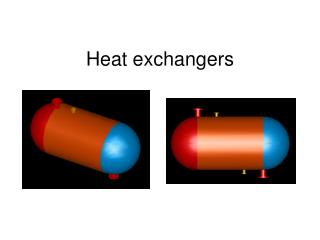
Heat Exchangers. Chapter 11 Section 11.1 through 11.4. Lecture 16. Parallel Flow. Counterflow. 1. Heat Exchanger Types. Classified according to flow types & constructions:. Finned-Both Fluids Unmixed. Unfinned-One Fluid Mixed the Other Unmixed. Heat Exchanger Types.

Heat Exchangers
E N D
Presentation Transcript
Heat Exchangers Chapter 11 Section 11.1 through 11.4 Lecture 16
Parallel Flow Counterflow 1. Heat Exchanger Types Classified according to flow types & constructions:
Finned-Both Fluids Unmixed Unfinned-One Fluid Mixed the Other Unmixed Heat Exchanger Types
One Shell Pass and One Tube Pass Heat Exchanger Types
Heat Exchanger Types One Shell Pass, Two Tube Passes Two Shell Passes, Four Tube Passes
2. Overall Heat Transfer Coefficient Definition of overall heat transfer coefficient U q ≡ UAT U = 1/(A*Rtot) Finned: Unfinned Tubular:
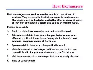
3. Heat Exchanger Analysis Objectives: To establish relationship between heat transfer rate with process parameters and heat exchanger configuration parameters. q = f (T, U, A) Tools: Energy balance Methods: Log-Mean, ε-NTU
Energy Balance Overall energy balance of hot fluid: Overall energy balance of cold fluid:
Energy Balance
Parallel-Flow Heat Exchanger • Many assumptions to simplify the solution; • Energy balance over control volume; • Define log-mean temperature difference; • Apply log-mean T in heat exchanger calculation.
Parallel-Flow Heat Exchanger where Ch and Cc are hot and cold Fluid Heat Capacity Rates.
Special Operating Conditions • Case (a): Ch>>Cc or h is a condensing vapor (Ch) • Negligible or no change in Th • Case (b): Cc>>Ch or c is an evaporating liquid (Cc) • Negligible or no change in Tc • Case (c): Ch=Cc ; .T1= .T2
Multipass and Cross-flow Heat Exchanger F for different flow arrangements can be found in figures 11S.1-11S.4
Example 11.1 A counterflow, concentric tube heat exchanger is used to cool the lubricating oil for a large industrial gas turbine engine. The flow of cooling water through the inner tube (Di=25 mm) is 0.2 kg/s, while the flow rate of oil through the outer annulus (Do=45 mm) is 0.1 kg/s. The oil and water enter a temperatures of 100 and 30 C, respectively. How long must the tube be made if the outlet temperature of the oil is to be 60 C?
Example 11.1 Known:Fluid flow rates and inlet T for counterflow, concentric tube heat exchanger of prescribed inner and outer diameter Find: Tube length to achieve a desired hot fluid outlet T Schematic:
Example 11.1 Assumptions: Negligible heat loss to environment Negligible kinetic and potential energy changes Constant properties Negligible tube wall thermal resistance and fouling factors Fully developed conditions for both fluids Properties: For oil, find cp, μ and k values from Table A.6 For Water, outlet T is unknown, assume find cp, μ, k and Pr values from Table A.6
Example 11.1 Analysis: 1. Calculate q and solve Tc,o from energy balance
Example 11.1 2. Establish relationship between q and U, A q, Di and are known, U can be calculated from hi and ho U = 1/(1/hi + 1/ho)
Example 11.1 3. Calculation of hi for forced convection in a tube Calculate ReD = 4 /(Diμ)=14050 (turbulent flow) From Eqn. 8.60, NuD=0.023ReD4/5Prn (n=0.4 for heating) NuD=90, hi = NuD*(k/Di) = 2250 W/m2K
Example 11.1 4. Calculation of ho for forced convection in an annulus Dh = Do-Di Calculate ReD = um Dh/μ=56.0 (laminar flow) From Table 8.2, Di/Do = 0.56, Nui=hoDh/k = 5.56 ho= Nui*(k/Dh) = 38.4 W/m2K
Example 11.1 5. Calculation U and L U=1/(1/hi + 1/ho )= 37.8 W/m2K
Example 11.2 A shell-and-tube heat exchanger must be designed to heat 2.5 kg/s of water from 15C to 85 C. The heating is to be accomplished by passing hot engine oil, which is available at 160 C, through the shell side of the exchanger. The oil is known to provide an average convection coefficient ho=400 W/m2K on the outside of the tubes. Ten tubes pass the water through the shell. Each tube is thin walled, of diameter of D=25mm, and makes eight passes through the shell. If the oil leaves the exchanger at 100 C, what is its flow rate? How long must the tubes be to accomplish the desired heating?
Example 11.2 Known:Fluid inlet and outlet Ts for a shell-and-tube heat exchanger with 10 tubes making eight passes Find: Oil flow rate required to achieve specified outlet T Tube length required to achieve the specified water heating Schematic:
Example 11.2 Assumptions: Negligible heat loss to environment Negligible kinetic and potential energy changes Constant properties Negligible tube wall thermal resistance and fouling factors Fully developed conditions for both fluids Properties: For oil, find cp, value from Table A.6 For Water, find cp, μ, k and Pr values from Table A.6
Example 11.2 Analysis: 1. Calculate q and solve from energy balance
Example 11.2 2. Establish relationship between q and U, A q, Di and are known, U can be calculated from hi and ho U = 1/(1/hi + 1/ho)
Example 11.2 3. Calculation of hi for forced convection in a tube Calculate ReD = 4 mc/(Dμ)=23234 (turbulent flow) From Eqn. 8.60, NuD=0.023ReD4/5Prn (n=0.4 for heating) NuD=119, hi = NuD*(k/D) = 30610 W/m2K
Example 11.2 4. Calculation U U=1/(1/hi + 1/ho )= 354 W/m2K 5. Find out F from Chart 11.10 P = (to-ti)/(Ti-ti) = (85-15)/(160-15)=0.48 R =(Ti-To)/(to-ti)=(160-100)/(85-15)=0.86 F ≈ 0.87
Example 11.2 6. Calculation L