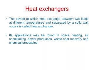
HEAT EXCHANGERS
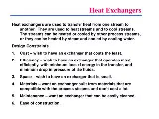
HEAT EXCHANGERS. Day 2. Heat Exchanger Types. The Overall Heat Transfer Coefficient. Rf ” are fouling factor . They are very important in process maintenance. Heat Exchanger Analysis. UA-LMTD METHOD When LMTD can be fixed Operational data are taken from PFD (Process Flow Diagram)


HEAT EXCHANGERS
E N D
Presentation Transcript
HEAT EXCHANGERS Day 2
The Overall Heat Transfer Coefficient Rf” are fouling factor. They are very important in process maintenance.
Heat Exchanger Analysis • UA-LMTD METHOD • When LMTD can be fixed • Operational data are taken from PFD (Process Flow Diagram) • Known as ‘Sizing Problem’ • e-NTU METHOD • When LMTD can not be fixed • Geometrical data are taken from heat exchanger detail • Know as ‘Rating Problem’
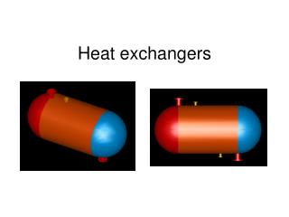
UA-LMTD METHOD LMTD DTLM Parallel-Flow and Counter-flow Heat Exchanger
UA-LMTD METHOD Special Operating Conditions
UA-LMTD METHOD Multipass and Cross-flow Heat Exchangers F is a correction factor that compensate ‘non ideal’ flow Which should be either parallel or counter-flow
Example A counterflow, concentric tube heat exchanger is used to cool the lubricating oil for a large industrial gas turbine engine. The flow rate of cooling water through the inner tube (Di = 25 mm) is 0,2 kg/s, while the flow rate of oil through the outer annulus (Do = 45 mm) is 0,1 kg/s. The oil and water enter at temperatures of 100 and 30oC, respectively. How long must the tube be made if the outlet temperature of the oil is to be 60oC.
ε is effectiveness of an heat exchanger. NTU = Number of Transfer Unit
Example 11.3 Hot exhaust gases, which enter a finned-tube, cross-flow heat exchanger at 300oC and leave at 100oC, are used to heat pressurized water at a flow rate of 1 kg/s from 35 to 125oC. The exhaust gas specific heat is approximately 1000 J/kg.K, and the overall heat transfer coefficient based on the gas-side surface area is Uh = 100 W/m2.K. Determine the required gas-side surface area Ah using the NTU method.
Compact Heat Exchangers • Both methods can be applied to analyze compact heat exchanger • Special care must be taken when evaluating fin-side convection heat transfer coefficient • Internal side convection heat transfer coefficient is calculated in the same way as the others heat exchanger type • Convection heat transfer coefficient is usually presented in graphical form for Colburn j Factor (jh) versus Reynolds Numer (Re)
Example 11.4 • Consider the heat exchanger design of Example 11.3, that is, a finned-tube, cross-flow heat exchanger with a gas-side overall heat transfer coefficient and area of 100 W/m2.K and 40 m2, respectively. The water flow rate and inlet temperature remain at 1 kg/s and 35oC. However, a change in operation conditions for the hot gas generator causes the gases to now enter the heat exchanger with a flow rate of 1.5 kg/s and a temperature of 250oC. What is the rate of heat transfer by the heat exchanger, and what are the gas and water outlet temperature?
Another Example Steam in the condenser of a power plant is to be condensed at a temperature of 30°C with cooling water from a nearby lake, which enters the tubes of the condenser at 14°C and leaves at 22°C. The surface area of the tubes is 45 m2, and the overall heat transfer coefficient is 2100 W/m2·°C. Determine the mass flow rate of the cooling water needed and the rate of condensation of the steam in the condenser.
Assumption: 1 Steady operating conditions exist. 2 The heat exchanger is well insulated so that heat loss to the surroundings is negligible and thus heat trans-fer from the hot fluid is equal to the heat transfer to the cold fluid. 3 Changesin the kinetic and potential energies of fluid streams are negligible. 4 There isno fouling. 5 Fluid properties are constant. Properties: The heat of vaporization of water at 30°C is hfg = 2431 kJ/kg and the specific heat of cold water at the average temperature of 18°C is Cp = 4184J/kg · °C (Table A–9). Analysis: The schematic of the condenser is given in Figure 13–19. The condenser can be treated as a counter-flow heat exchanger since the temperature of one of the fluids (the steam) remains constant. The temperature difference between the steam and the cooling water at the two ends of the condenser is:
Then the heat transfer rate in the condenser is determined from, Q = UAsΔTlm = 2100 W/m2· °C)(45 m2)(11.5°C) = 1.087 x10⁶W = 1087 kW Therefore, the steam will lose heat at a rate of 1,087 kW as it flows through the condenser, and the cooling water will gain practically all of it, since the con-denser is well insulated. The mass flow rate of the cooling water and the rate of the condensation of thesteam are determined from Q·= [m·Cp(ToutTin)]cooling water = (m·hfg)steam to be