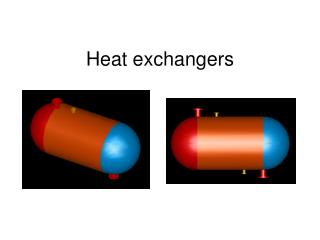
Heat Exchangers
Heat Exchangers. Design Considerations. Heat Exchangers. Key Concepts Heat Transfer Coefficients Naming Shell and Tube Exchangers Safety In Design of Exchangers Controls for Exchangers. Heat Exchangers. 4. Key Concepts. "Allow me to summarise:


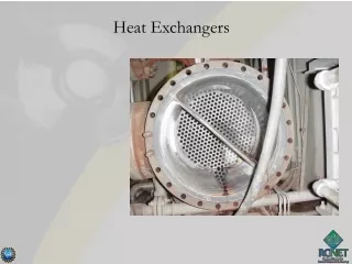
Heat Exchangers
E N D
Presentation Transcript
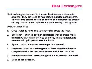
Heat Exchangers Design Considerations
Heat Exchangers • Key Concepts • Heat Transfer Coefficients • Naming Shell and Tube Exchangers • Safety In Design of Exchangers • Controls for Exchangers
4 Key Concepts "Allow me to summarise: Hot stuff this side, cold stuff that side. Make the cold stuff hotter, but use inbetween stuff to not let the cold stuff actually touch the hot stuff. Cold stuff and hot stuff not allowed to destroy inbetween stuff and vice versa. Some kinds of inbetween stuff works better than others. Might need pumps or fans to make the whole shebang work a little better, too.” - Topher Gayle
General Sizing Method • Pick an exchanger type (S&T, Plate & Frame etc.) • Choose counter or co-current flow • Choose number of tube passes (for S&T) • draw Temp diag, Calculate the LMTD and Q • Calculate the LMTD Correction Factor (F) if more than two tube passes • Choose a U value based on tables • Calculate the Area , A = Q/ U LMTD F • Perform rigorous rating as required (not 470)
8-9 Key Concepts = Heat Lost Heat Transfer Heat Absorbed Q = U A Tln Either Q = m Cp T, or Q = m Hevap Either Q = m Cp T, or Q = m Hevap m Cp hot (T1-T2) = U A Tln = m Cp cold ( t1 - t2)
9 Combined Equations m Cp hot (T1-T2) = U A Tln = m Cp cold ( t1 - t2) • Calculate the unknowns • Determine the overall heat transfer coefficient (U) value in order to calculate the Area (A) to size the exchanger
Duty Considerations - Q • Distillation Columns • Start-up and Shut-down usually require the column to operate at “full reflux” • Feed and Outlets are shut down • 100% of Overhead vapour being condensed • 100% of reflux being boiled • Compositions can be completely different (reactor not online), therefore diff. temps • Is the duty in the simulation truly the worst-case duty? • For our purposes assume yes
T1 t2 Counter Current Exchanger Temp Profile t1 T1 t2 T2 T2 t1 26-27 Mean Temp Difference Always Draw This Graph !!
200 Exchanger Temperature Profile T1 Hot Side temp & flow direction T2 Cold Side temp & flow direction t2 30 45 38 t1 26-27 Mean Temp Difference • Correction for not strictly counter or co- current flow
T1 = 200 t2 = 45 T2 = 38 t1 = 30 27-28 Temperature Correction Factor • Form of the heat transfer equations is: • The factor F is usually determined Graphically T1 = 200 T2 = 38 t1 = 30 t2 = 45 As A Single Pass Counter Current - temp cross?
27-28 Temperature Correction Factor • Form of the heat transfer equations is: • The factor F is usually determined Graphically T1 = 200 T2 = 38 t1 = 30 t2 = 45 T1 = 200 As a 2 Pass exch - temp cross - low F factor t2 = 45 T2 = 38 t1 = 30
28-39 Temperature Correction Factor R = 11.2, P = 0.0882 , F = 0.471
30 Condensing LMTD • Divide the Exchanger into segments • Evaluate U and LMTD for each segment • Multicomponent, noncondensables? Arghh!
Counter to the Co-current • Use Counter Current • maximize LMTD (minimize Area, cost etc.) • minimize utility reqt’s • Use Co-current • minimize outlet utility temperatures during turn down - see later • reduced fouling
9-11 Determining U • Tables for U values • Determine U via fundamental equations • note that fouling factors often overshadow much of the accuracy that the fundamental equations provide • Details of exchanger configuration required • Computer Programs / Vendors • vendors can and will provide exch sizing • Be knowledgeable enough to critique their design
11-13 Determining U • Physical configuration affects U values • Tables assume certain things about the exchanger. If through poor configuration, (ie..inappropriate tube length, or number of tubes) the assumptions are invalidated, then the tables will mislead.
11-13 U Values & Velocity
11-13 Physical Config & U Values The following factors all affect the velocities of the fluids in the exchanger • Tube Length • Tube Dia • Number of Tube Passes • Number of Tubes / Bundle dia • Baffle Spacing Note: This does not apply to condensers or boiling
11-13 U Values & Velocity • Adding a Tube Pass doubles the velocity of the liquid on the tube side • Decreasing Baffle Spacing Increases Velocity Shellside
Physical Configuration & U values • Tube Layout Triangular (high heat x-fer) Square Rotated Square Preferred for cleaning 26
13 Velocity Limitations • Maximum Velocity is Dictated by: • Vibration • Erosion • Hydraulic • Exchanger Physical Size
13-15 Velocity Limitations - Vibration • Usually a Shell Side Issue • Vibration Can Cause • Collision Damage, Baffle Damage, Fatigue & Tubejoint Failure • Causes • Turbulent buffeting • Fluidelastic whirling • Vibration induced by flow parallel to the tubes
13-15 Velocity Limitations - Vibration • Analysis • determine the natural frequency of the tubes • vibration of tubes between baffles • vibration on U bends • account for damping (fluid properties, tube stresses etc.) • determine critical flow velocity • minimum cross flow velocity that the span may vibrate unacceptably large amplitudes. • Analysis by Programs or TEMA Standards
15 Tube Side Velocity Limitations - Erosion • High Velocity causes thinning of the metal walls (erosion). • It can be avoided by maintaining velocities (ft/sec) below those given by this equation. (about 12 ft/sec for water) • TEMA say ru2 < 6000 to eliminate tube end erosion
15-16 Velocity Limitations - Hydraulics • Available pressure drop will limit velocity • The P rises to the square of the velocity 60 psig EXCH 0 psig CV P
16-17 Velocity Limitations - Physical • Limitations on Shipping, • Floor space etc. all make a difference (don’t forget about pulling the tube bundle)
U values of interest • Condensing U values are very high (500 to 800) • Reboiler U values are very high ( 700) • liq / liq U values in middle (100 - 300) • Cooling / heating gases (desuperheating) have very low U values (<30)
Shell Side Fluid Leaks to Atmosphere TEMA Easier to Clean Expensive Large Annular Space = Low U Value Less Costly Cheap, Hard to clean
Exchanger Selection • Require a U-tube or Floating head, instead of fixed tube sheet, when thermal expansion between shell and tubes is an issue • i.e. shell side fluid and tube side fluid temperatures differ by more than 200 °F • Require a Floating Head, instead of U-tube • When cleaning tubes mechanically is important (dirty fluids on tube side) • When errosion may occur on tube side
Nucleate Boiling Film Boiling 52 Reboilers • Boiling Phenomena • Nucleate boiling at shell/tube T = 20 to 50 °F
53-57 Reboilers • Sizing • Common to use “maximum heat flux” • 15,000 BTU/hr sq ft • Fundamental Equations can be used to determine the best DT • Max Flux is a function of the Number of active nucleation which is in turn affected by the materials of construction, the fluid properties and the temperature difference
55 Reboilers • Heat Flux can be increased with special systems (i.e. sintering, brazing, flame spraying, electrolytic deposition). Sand blasting , scoring tends not to provide stable long term enhancement. Trapped Vapour Nucleation Sites
Heat Exchanger Safety • What Can Fail? • Control System Failure • Shell & Tube • Tube can rupture • Tubes separate from Tube Sheet • Blocked in exchanger causes cool fluid to experience temperatures of hot fluid • Plate & Frame • Gaskets can leak mixing hot and cold sides , or releasing either fluid to surroundings
Heat Exchanger Safety • Implications • Fires, Explosions, Toxic Releases
Design Duty Reduced Duty Hot In Hot In Cold Out Cold Out Hot Out Hot Out Q = m c T Cold In Cold In Controlling Exchangers Q = U A Tln • A is fixed • U varies slightly with velocity • Tln is the controlling variable
58 Controls • Liquid / Liquid - control on cooling media C/w
59 Controls • Liquid / Liquid - control on process C/w
60 Controls - Steam Heating • Steam Pressure Control T
61 Controls - Steam Heating • Condensate Level Control
Duty: 153 x 106 KJ/hr T1 = 213.3 °C T2 = 35 °C t1 = 30 °C dew point: 150 °C (to be confirmed in PRO 2) U gas/water - 0.51 kW/ m2 °C U condensing / water - 0.85 kW/ m2 °C Workshop - Size “Condenser”