Download
1 / 15
160 likes | 247 Vues
Explore the status and progress of the silicon detector configuration for the Si-tracker at Victoria, focusing on layout options, support structures, segmented barrels and disks configuration. Detailed analysis and modifications to enhance accessibility, noise figures, alignment, and potential expansion are discussed in this report.

E N D
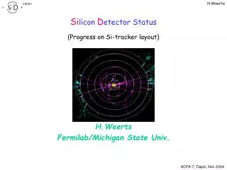
Silicon Detector Status (Progress on Si-tracker layout) H.Weerts Fermilab/Michigan State Univ.
Status around July 2004 Two layout options considering at very schematic stage Barrels vary in length, barrel –forward transition at fixed q angle Barrels with same length, with same size radius disks at the end This configuration slight prefered
Support structures At Victoria, introduce Carbon Fiber cylinders for support…. now default Initially sensors mounted triangular support structure Long ladders split at z=0. Long ladders still an option, but evolved to shorter structures ( ~10cm) & cylinder support Thickness: 300m Si= 0.45% + CF = 0.2% X0
Layout at Victoria 1 • Barrels • Five barrels • Measure Phi only • Eighty-fold phi segmentation • Barrel lengths increase with radius • Maximum active radius = 1.240 m • Minimum active radius = 0.218 m • Maximum active length = 3.307 m • Disks • Five double-disks per end • Measure R and Phi • Disk radii increase with Z • Maximum active radius = 1.262 m • Minimum active radius = 0.041 m • Maximum Z (active) = 1.687 m • Minimum Z (active) = 0.282 m
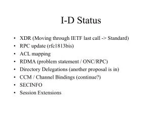
Layout at Victoria 2 At Victoria presented a compete mechanical layout with sensor sizes: 80 segmentation in phi, 10 cm long sensors in z. Presented calculated noise figures: For T=20oC and –10oC
Start changing layout Requirement: vertex detector should be accessible for installation and repair without removing beam pipe. This requires that silicon tracker is able to slide in “z” to give access to vertex detector. After some iterations…
Modification of earlier Proposal • Outer tracker slides over inner tracker in either direction • Disks carried by the beam tube assembly are offset in Z to provide overlap with corresponding outer tracker disks • 5 mm clearance from silicon cut edge to silicon cut edge
Slight Modification of Earlier Proposal (3) • Outer tracker slides over inner tracker in either direction • Disks carried by the beam tube assembly are offset in Z to provide overlap with corresponding outer tracker disks • However, layer-to-layer support connections are projective • CF connecting disks can have spokes rather than being contiguous • Ball mounts and spokes need not align in azimuth
Non projective supports Modification to Reduce Alignment of Material • One sensor added to barrels 1, 2, and 4 (each side of Z = 0) • No disk attached to barrel 1 • Still projective from barrel 3 to barrel 5
Non projective barrel supports What Happens if Barrels are Extended? • Disk tracks pass through barrel layers at relatively shallow angles
Observations • We need a proper calculation of the number of radiation lengths. • Overlap regions in the design with stepped barrel lengths do not appear to be so bad as one might have feared. • Each design has appealing features. • Ease of assembly and servicing are important factors.
Add layers …. Proposals: • to add more layers are being studied. • Vary thickness of silicon from thin (50m) to 300m towards outer radius • 8 layer nearly continuous Other ideas: • Add stereo layers
Comparison 8 layers Eight-Layer “Fantasy” Tracker • Most precise design for p • Cross-over with ‘Fantasy Tracker’ at 90 GeV/c • Cross-over with TPC at 10 GeV/c SD Thin: 5 layers, no support, 100, 100, 200, 200, 300mm sensors in layers 1 –5. ( total 1.9% X0) SD Thick: 1.5%X0/layer ( 5 layers; 7.5%X0) “Fantasy”: total 3.7%X0 (no support)
Conclusion The Si tracker layout in SiD is being actively worked on. Taking into consideration installation and access requirements Also looking into variations of the “5 layer” starting point