Download
1 / 27
310 likes | 548 Vues
( Session 23 - Cathodes II ). 13:40 Thursday, 30 April 2009. High Current Density and Long Life Nanocomposite Scandate Dispenser Cathode Fabrication. Jinfeng Zhao, Larry Barnett, and Neville C. Luhmann Jr. Department of Applied Science, University of California-Davis (UCD), CA 95616, USA

E N D
(Session 23 - Cathodes II) 13:40 Thursday, 30 April 2009 High Current Density and Long Life Nanocomposite Scandate Dispenser Cathode Fabrication Jinfeng Zhao, Larry Barnett, and Neville C. Luhmann Jr. Department of Applied Science, University of California-Davis (UCD), CA 95616, USA Na Li and Ji Li Beijing Vacuum Electronics Research Institute, Beijing, China 10th International Vacuum Electronics Conference (IVEC2009) April 28 - 30th 2009
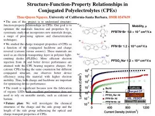
Why W-Sc Nanopowder Cathodes ? • Millimeter/THz sources require reduced cathode area and low to moderate beam • compression →high current density fully space charge limited operation:30 -100+ A/cm2 • Gyro-TWTs at W-Band and beyond require smooth surfaces for reduced velocity • spread (proportional to roughness(1/2)), uniform emission, and high current density: • 40+ A/cm2 • End of tube life often due to barium deposits leading to arcing as well as Ba depletion • →low temp. operation critical (lifetime improvement by x4 for each 50 °C reduction) • Long lived HPM cathodes for conditioning and rep rated operation: 100+ A/cm2
Gyro-TWT Performance Dependence on Beam Quality • Nonlinear large signal code predicts output power, efficiency and gain For predicted velocity spreadDvz/vz = 5% -BandwidthDw/w = 5% - Pout= 110 kW - h = 22% - Large signal gain = 45 dB
Impact of Cathode Roughness on MIG* Beam Velocity Spread Conventional Scandate Cathode W-Sc Nanopowder • New UCD MIG Design: 50 degree cathode with compression of only 12 (Bgun=3.0 kG). • EGUN gives 3.9% axial spread and 1.7% transverse spread.
BVERI-BJUT W-Sc Nanopowder Cathode Concept Data from Beijing Vacuum Electronics Research Institute (BVERI) & Beijing University of Technology (BJUT) 500 hours achieved at 100 A/cm2 in tests at SLAC • Benefit of adding scandia into nano tungsten powder by chemical synthesis • Improve emission uniformity. • Increase emission capability. • Resist ion bombardment. • Nano sized scandia-doped tungsten powder • Combined by aqueous solution method (Liquid-solid or Liquid-liquid ) • Spherical tungsten grains • Scandium oxide absorb on the surface of spherical tungsten grains. • Sc-W powders with more uniformly distributed Sc2O3 were obtained • Space charge limited • current densities of more • than 30 A/cm2 at 850 oCb achieved
Nano Composite Cathode Fabrication—UCD Sol-Gel Process Optimize Nano composite Sc2O3-doped W matrix 1. Nano Sc2O3-doped W powder Fabrication
Nano Sc2O3-added W Powder Fabrication—UCD Sc2O3-added Wpowders SEM Results
Nano Sc2O3-added W Powder Fabrication—UCD Sc2O3-added Wpowders SEM Results
Nano Sc2O3-added W Powder Fabrication—UCD Sc2O3-added Wpowders SEM Results
Nano Sc2O3-added W Powder Fabrication—UCD Sc2O3-added Wpowders SEM Results
Nano Sc2O3-added W Powder Fabrication—UCD Sc2O3-added Wpowders SEM Results
Nano Sc2O3-added W Powder Fabrication—UCD Conclusions: Uniform Nano Sc2O3-doped W powder has been made with different particle size, such as average particle size around 72 nm, 146 nm, 272 nm, and 614 nm, respectively.
Sc2O3-added W Matrix — UCD TopSurface By using 72 nm initial nano powder After Regular Furnace Sinter Grain size in matrix is 400-500 nm Pore size ~ 400 nm CrossSection
Sc2O3-added W Matrix — UCD TopSurface By using 272 nm initial nano powder After Regular Furnace Sinter Grain size in matrix is 500-600 nm Pore size ~ 400 nm CrossSection
Sc2O3-added W Matrix — UCD TopSurface By using 587 nm initial nano powder After Regular Furnace Sinter Grain size in matrix is 1 – 2 µm Pore size ~ 0.5 µm CrossSection
Sc2O3-added W Cathode — UCD SEM images on the top surface of UCD cathode After Furnace Sinter: Average grain size in cathode is 600 nm and very uniform
Sc2O3-added W Cathode — UCD SEM images on the top surface of UCD cathode After Furnace Sinter: Average grain size in cathode is 700 nm and very uniform
Sc2O3-added W Cathode — UCD SEM images on the top surface of UCD cathode After Furnace Sinter: Average grain size in cathode is 900 nm and very uniform
Cathode Testing at BVERI Current Density vs Cathode Button Voltage J = 73.56 A/cm2 , 1000 °C Using UC Davis Material
Cathode Testing at UC Davis Cathode Testing New High Perveance Cathode Life Test Vehicle Multiple rapid cathode life test facility Rapid button test System operational Cathode testing and life testing underway at UC Davis: eight vehicles operational with another four nearing completion G. Scheitrum and A. Hasse Three 3.0 P CLTVs completed
Cathode Testing at UC Davis Current Density versus Cathode Button Voltage • Comparison: • Spectra-mat 311X 20 A/cm2 at 1150 °C • UCD cathode: 80 A/cm2 fully space charge limited
Cathode Testing at UCD Current Density vs Cathode Button Voltage UC Davis Pellet impregnated by Spectra-Mat
Interpretation of Cathode Testing Results at UC Davis • The 1150o C data increases to 40 A/cm2 and drops slightly from the SCL line (slope of 1.5),then continues to 80 A/cm2 at a slope of 1.5 (full space charge limited). • Interpreted as field emission in the high current range where the deviation from the ideal SCL (zero extraction voltage) is not a drop in emission current capability, but a drop in the actual space charge limited current due to the required extraction field.
Interpretation of Cathode Testing Results at UC Davis • Speculate that field emission points are formed: • The optimum point formation, density of points and/or sharpness of the points, is at ~1150o Cb • The initial activation is very fast at ~1150o Cb and minimal at < 1100o Cb • Assuming the point density is proportional to the number of grains leads to the conclusion that smaller grains will have more points and the cathode will have higher emission density up to the limit that it starts decreasing the field on each point and limiting total emission. Hence, there is a maximum grain-point density (under study)
Sumitomo SPS-2050 Cathode Testing Summary • Summary of cathode testing: • 80 A/cm2 fully space charge limited current density has been obtained at 1150 oCb • Cathode life testing has been at 1150 oCb for 800 h following 768 h at 950 oCb • Cathode made by smaller particles had 50/cm2 emission at 1050 oCb • Future Plans for cathode testing: • Investigate performance of cathodes made by different initial Sc2O3-W nanopowder average particle sizes: 100, 300, 500 nm, etc. • Cathodes made with different porosities • Cathodes made with different Sc2O3 concentrations • Investigate robustness with respect to reactivation • Conduct life tests in new 3.0 P CLTV’s • Spark plasma sintering Spark Plasma Sintering
Thank You Work supported by: • AFOSR under Grant F9550-99-04-1-0353 (MURI04 “NanoPhysics of Electron Dynamics near Surfaces in High Power Microwave Devices and Systems”) • NSWC Crane • HiFIVE DARPA, Contract No. G8U543366, through a subcontract from Teledyne Scientific.
100 kV,a=1.0 200 TE02(2) 150 operating point (grazing intersection) w/2p (GHz) s=2 s = 2 100 TE01(1) w = sWc + kzvz TE21(1) 50 s=1 s = 1 TE11(1) w = sWc + kzvz Potential Gyro-BWO interaction -4000 4000 0 kz(/m) 27/34 TE01 Gyro-TWT Dispersion Diagram • Beam mode dispersion: w = sWc + kzvz • Wave mode dispersion: w2 = wc2 +c2kz2 • Absolute instabilities must be stabilized • : TE11(1), TE21(1), TE02(2) ,TE01(1)