The Basic Principles of OFDM
390 likes | 1.6k Vues
The Basic Principles of OFDM. Gwo-Ruey Lee. Outlines. The Basic Principles of OFDM [1-7] FFT-based OFDM System Serial and Parallel Concepts [1,7] Modulation/Mapping [10,11] M -ary Phase Shift Keying M -ary Quadrature Amplitude Modulation IFFT and FFT [8,9]

The Basic Principles of OFDM
E N D
Presentation Transcript
The Basic Principles of OFDM Gwo-Ruey Lee
Outlines • The Basic Principles of OFDM [1-7] • FFT-based OFDM System • Serial and Parallel Concepts [1,7] • Modulation/Mapping [10,11] • M-ary Phase Shift Keying • M-ary Quadrature Amplitude Modulation • IFFT and FFT [8,9] • Signal Representation of OFDM using IDFT/DFT • Orthogonality [1-7] • Guard Interval and Cyclic Extension [1-7] • Advantages and Disadvantages [1,4,7]
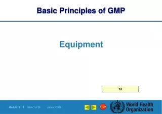
Fast Fourier Transform Subchannels Guard Intervals Frequency Symbols Channel Time x bits Serial Data Input Serial-to-Parallel Converter Signal Mapper IFFT Parallel- to-Serial Converter Guard Interval Insertion D/A & Low pass Filter Up- Converter x bits Signal Demapper Parallel- to-Serial Converter One-tap Equalizer FFT Serial-to-Parallel Converter Guard Interval Removal A/D Down- Converter Serial Data Output FFT-based OFDM System 1/3
FFT-based OFDM System OFDM Transmitter 2/3 x1=[0,0] d1=1 x2=[0,1] d2=i x=[0,0,0,1,1,0,1,1,….] x3=[1,0] d3=-1 x4=[1,1] d4=-i …..
FFT-based OFDM System OFDM Transmitter 3/3 CP CP CP CP DATA CP
Series and Parallel Concepts 1/3 • In OFDM system design, the series and parallel converter is considered to realize the concept of parallel data transmission.
Series and Parallel Concepts 2/3 • Series • In a conventional serial data system, the symbols are transmitted sequentially, with the frequency spectrum of each data symbol allowed to occupy the entire available bandwidth. • When the data rate is sufficient high, several adjacent symbols may be completely distorted over frequency selective fading or multipath delay spread channel.
Series and Parallel Concepts 3/3 • Parallel • The spectrum of an individual data element normally occupies only a small part of available bandwidth. • Because of dividing an entire channel bandwidth into many narrow subbands, the frequency response over each individual subchannel is relatively flat. • A parallel data transmission system offers possibilities for alleviating this problem encountered with serial systems. • Resistance to frequency selective fading
Modulation/Mapping 1/1 • The process of mapping the information bits onto the signal constellation plays a fundamental role in determining the properties of the modulation. • An OFDM signal consists of a sum of sub-carriers, each of which contains M-ary phase shift keyed (PSK) or quadrature amplitude modulated (QAM) signals. • Modulation types over OFDM systems • Phase shift keying (PSK) • Quadrature amplitude modulation (QAM)
Mapping - Phase Shift Keying 1/2 • M-ary phase shift keying • Consider M-ary phase-shift keying (M-PSK) for which the signal set is where is the signal energy per symbol, is the symbol duration, and is the carrier frequency. • This phase of the carrier takes on one of the M possible values, namely , where
Mapping - Phase Shift Keying 2/2 • An example of signal-space diagram for 8-PSK .
Mapping – Quadrature Amplitude Modulation 1/2 • The transmitted M-ary QAM signal for symbol i can be expressed as where E is the energy of the signal with the lowest amplitude, and , and are amplitudes taking on the values, and, where M is assumed to be a power of 4. • The parameter a can be related to the average signal energy ( ) by
Mapping – Quadrature Amplitude Modulation 2/2 • An example of signal-space diagram for 16-square QAM.
IFFT and FFT 1/1 • Inverse DFT and DFT are critical in the implementation of an OFDM system. • IFFT and FFT algorithms are the fast implementation for the IDFT and DFT. • In the IEEE 802.11a, the size of IFFT and FFT is N=64.
Signal Representation of OFDM using IDFT/DFT 1/2 • Signal representation of OFDM using IDFT/DFT • Now, consider a data sequence , and , where , , and is an arbitrarily chosen symbol duration of the serial data sequence .
Signal Representation of OFDM using IDFT/DFT 2/2 • If these components are applied to a low-pass filter at time intervals
Orthogonality 2/2 • Digital communication systems • In time domainIn frequency domain • OFDM • Two conditions must be considered for the orthogonality between the subcarriers. • 1. Each subcarrier has exactly an integer number of cycles in the FFT interval. • 2. The number of cycles between adjacent subcarriers differs by exactly one.
Orthogonality 2/2 Time domain Frequency domain Example of four subcarriers within one OFDM symbol Spectra of individual subcarriers
Guard Interval and Cyclic Extension 1/7 • OFDM symbol • OFDM symbol duration .
Guard Interval and Cyclic Extension 2/7 • Two different sources of interference can be identifiedin the OFDM system. • Intersymbol interference (ISI) is defined as the crosstalk between signals within the same sub-channel of consecutive FFT frames, which are separated in time by the signaling interval T. • Inter-carrier interference (ICI) is the crosstalk between adjacent subchannels or frequency bands of the same FFT frame.
Guard Interval and Cyclic Extension 3/7 • Delay spread
Guard Interval and Cyclic Extension 4/7 • For the purpose to eliminate the effect of ISI, the guard interval could consist of no signals at all. • Guard interval (or cyclic extension) is used in OFDM systems to combat against multipath fading. :guard interval :multi path delay spread • In that case, however, the problem of intercarrier interference (ICI) would arise. • The reason is that there is no integer number of cycles difference between subcarriers within the FFT interval.
Guard Interval and Cyclic Extension 5/7 • To eliminate ICI, the OFDM symbol is cyclically extended in the guard interval. • This ensures that delayed replicas of the OFDM symbol always have an integer number of cycles within the FFT interval, as long as the delay is smaller than the guard interval.
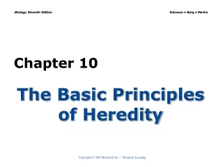
Subcarrier #1 Delayed subcarrier #2 Guard time FFT integration time=1/carrier spacing Guard time FFT integration time=1/carrier spacing OFDM symbol time OFDM symbol time Guard Interval and Cyclic Extension 6/7 • Effect of multipath with zero signals in the guard interval, the delayed subcarrier 2 causes ICI on subcarrier 1 and vice versa. Part of subcarrier #2 causing ICI on subcarrier #1
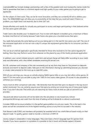
Subchannels 1/T Tg Fast Fourier Transform T Guard Intervals Frequency Symbols Time Guard Interval and Cyclic Extension 7/7 • Time and frequency representation of OFDM with guard intervals.
Advantages and Disadvantages 1/3 • Advantages • Immunity to delay spread • Symbol duration >> channel impulse response • Guard interval • Resistance to frequency selective fading • Each subchannel is almost flat fading • Simple equalization • Each subchannel is almost flat fading, so it only needs a one-tap equalizer to overcome channel effect. • Efficient bandwidth usage • The subchannel is kept orthogonality with overlap.
Advantages and Disadvantages 2/3 • Disadvantages • The problem of synchronization • Symbol synchronization • Timing errors • Carrier phase noise • Frequency synchronization • Sampling frequency synchronization • Carrier frequency synchronization • Need FFT units at transmitter, receiver • The complexity of computations
Advantages and Disadvantages 3/3 • Sensitive to carrier frequency offset • The effect of ICI • The problem of high peak to average power ratio (PAPR) • Problem 1. It increased complexity of the analog-to-digital and digital-to-analog converters. • Problem2. It reduced efficiency of the RF power amplifier. • The solutions • 1.Signal distortion techniques,which reduce the peak amplitudes simply by nonlinearly distorting the OFDM signal at or around the peaks. • 2.Coding techniques using a special forward-error-correction code • 3. It is based on scrambling each OFDM symbol with different scrambling sequences and then the sequence that gives the smallest PAP ratio is selected.
References • [1] Richard van Nee, Ramjee Prasad, OFDM wireless multimedia communication, Artech House Boston London, 2000. • [2] Ahmad R. S. Bahai and Burton R. Saltzberg, Multi-carrier digital communications - Theory and applications of OFDM, Kluwer Academic / Plenum Publishers New York, Boston, Dordrecht, London, Moscow, 1999. • [3] Ramjee Prasad, “OFDM based wireless broadband multimedia communication,” Letter Notes on ISCOM’99, Kaohsiung, Taiwan, Nov. 7-10, 1999. • [4] L. Hanzo, W. Webb and T. Keller, Single- and multi-carrier quadrature amplitude modulation – Principles and applications for personal communications, WLANs and broadcasting, John Wiley & Sons, Ltd, 2000. • [5] Mark Engels, Wireless Ofdm Systems: How to Make Them Work? Kluwer Academic Publishers. • [6] Lajos Hanzo, William Webb, Thomas Keller, Single and Multicarrier Modulation: Principles and Applications, 2nd edition, IEEE Computer Society. • [7] Zou, W.Y.; Yiyan Wu, “ COFDM: An overview ” Broadcasting, IEEE Transactions on, Vol. 41, Issue 1, pp. 1 –8, Mar. 1995. • [8] Emmanuel C. Ifeachor & Barrie W. Jervis, Digital signal processing – A practical approach, Addision-Wesley, 1993. • [9] Blahut, R. E., Fast Algorithms for digital processing. Reading, Ma: Addison-Wesley, 1985. • [10] Simon Haykin, Communication Systems, John Wiley & Sons, Inc., 3rd edition, 1994. • [11] Roger L. Peterson, Rodger E. Ziemer, David E. Borth, Introduction to spread spectrum communications, Prentice Hall International Editions, 1995.