Chapter 12.1: Media Access C ontrol (MAC) sublayer
Chapter 12.1: Media Access C ontrol (MAC) sublayer. LLC is similar to HDLC (book 11.6). Figure 12.2 Taxonomy of multiple-access protocols discussed in this chapter. Will only cover random-access protocols. Contention: Access to shared media. Problem:

Chapter 12.1: Media Access C ontrol (MAC) sublayer
E N D
Presentation Transcript
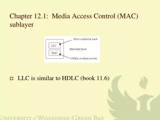
Chapter 12.1: Media Access Control (MAC) sublayer • LLC is similar to HDLC (book 11.6)
Figure 12.2 Taxonomy of multiple-access protocols discussed in this chapter Will only cover random-access protocols
Contention: Access to shared media • Problem: • two (or more devices) want to transmit over a shared baseband medium at the same time. • Collision • Transmissions collide, destroying the information in each transmission
Aloha protocol • University of Hawaii (where else) - packet switched radio (mid 70s). • Transmit a packet using a specified radio frequency • wait for ack • If the ack does not arrive send packet again because it probably collided with another station sending a packet over the same frequency.
Figure 12.4 Procedure for pure ALOHA protocol • Don’t worry yet about how TB is calculated
Figure 12.3 Frames in a pure ALOHA network wasted However, time from the start of 3.1 to the end of 1.2 is wasted time.
Figure 12.5 Vulnerable time for pure ALOHA protocol • Keep in mind even if a small part of a packet collides, the entire packet is of no use.
Slotted Aloha • Time divided into intervals of length Tfr, the time required to send one frame. • Device begins sending only at the start of an interval • Does not eliminate collisions, but • If two frames collide the wasted time is Tfr • With pure Aloha, it could be 2Tfr
CSMA (Carrier Sense Multiple Access) • Original Ethernet configured similar to that below • Only one device could transmit at a time • Refinement of Aloha protocols
If a device has something to send it will • Listen: if medium is quiet then send • if not quiet then wait for quiet. • Works most of the time • Two waiting devices could detect quiet at nearly the same time and their transmissions would collide
Figure 12.8 Space/time model of the collision in CSMA • I believe yellow represents B’s signal and blue represents C’s signal
P-persistence • when quiet, transmit with probability p • (i.e. p=1/2 => 50% chance of transmitting • Non-persistent: If busy, wait one time slot (time to transmit one frame) and try again. • Show examples showing all possible scenarios with two or three stations waiting via p-persistence with p=0.5.
CSMA/CD: • adds collision detection (CD). • Transmit and listen for collision. • If one occurs stop transmitting, wait random time and try again. • Reduces amount of time during which signals collide.
Requires a minimum frame size for CSMA/CD to work. • Device must still be sending when collision detected or else it does not know if its frame was involved.
Early Ethernet: • 10Mbps and 2 km cable • signal propagation speed was 200 meters/msec • Worst case: 10 msec to collision and 10 more to detect it. • Can send 200 bits in that 20 msec time. Must detect collision while frame is still being sent.
Binary exponential backoff algorithm • 1stcollisionwait 0/1 time slot (chosen randomly) • 2nd collision wait 0-3 time slots (chosen randomly) • 3rd collision wait 0-7 time slots (chosen randomly) • in general wait 0-2n-1 –1 time slots (chosen randomly). • After 16 collisions give up.
Section12.1 also discusses CSMA/CA (Collision Avoidance) • Somewhat different protocol used for 802.11 Wireless standards. • Covered later • Does not really avoid collisions.
Token ring and token bus (brief mention in section 12.1) • Tokens circulated among devices • A device with something to send waiting for the token • NO collisions • Needed management protocols if a problem occurred with the token • IEEE 802.4 and 802.5 are standards for token ring and bus networks • IEEE 802.3 Ethernet (actually its variations) is dominant
Ethernet Chapter 13 • There are numerous IEEE802.3 standards for Ethernet. • Standard Ethernet (10 Mbps) • Fast Ethernet (100 Mbps) • Gigabit Ethernet (1 Gbps) • Ten-Gigabit Ethernet (10 Gbps) • More than just bit rates - accounts for different media, signaling techniques, frame format, collision handling, etc.
Original IEEE 802.3 Ethernet design: • Nic: network interface card
Figure 13.4 802.3 MAC frame • Source and destination MAC (48-bit addresses) - groups assigned/controlled by IEEE
Computer executes network software and routes packet of info to memory and signals nic via internal bus • nic gets packet from memory, creates a frame, and waits for signal from transceiver • transceiver listens to cable. Quiet => signal nic to send data to transceiver; • transceiver transmits bits onto cable and listens for collision. • If collision occurs, nic executes binary exponential backoff algorithm. • If too many collisions => send message to network software
other transceivers copy a frame and send it to the nic. • If address in frame corresponds to nic address then do crc check. • If OK, signal computer that packet arrived. • Computer executes network software to determine whether packet can be accepted as per flow control. If so, move packet to memory.
Ethernet address: • 48 bits - burned into network card • A company that manufactures cards purchases a group of 224 addresses (managed by IEEE) [http://standards.ieee.org/regauth/oui/index.shtml] • Look up your physical address (ipconfig /all). Search for the OUI (Organizationally Unique Identifier) in the previous link. Just enter the first 6 hex digits in the form xx-xx-xx. Example: 00-19-D1. • Unicast address: identify one device • Multicast address: identify numerous (all - broadcast) devices
802.3 flavors • 802.3 • 10Base5, thick cable, • 500-meter segments • max of 5 segments (4 repeaters) in sequence • collision domain (span in which a collision can occur) is 2500 m. • Manchester coding, min. 8 ft between transceivers.
802.3a • 10Base2 • (Thinnet, CheaperNet) thinner cable • T-connectors, max of ~200 meter segments • 5 segments, collision domain ~1 km. • Cheaper & more flexible but shorter segments
802.3i • 10BaseT • CAT 3, 4, 5 UTP • central hub – device to regenerate and send signals • max UTP length is 100 m. collision domain ~500-2500 m (depends on delay at hubs) • Collisions still occur (in hub)
802.3j • 10BaseF • Fiber • Requires a 10-BaseF hub • max fiber length 2000 m.
Bridged Ethernet • Collisions can occur between any two devices – not ideal. • Bridge – layer 2 connector of two networks. • Only forwards a frame if the destination is on the other side • Also adds a little extra security since each frame does not go everywhere
Figure 13.16 Collision domains in an unbridged network and a bridged network
Switched Ethernet • Switch is like a bridge but with more connections • Otherwise, very similar • Could connect multiple switches
No collisions assumes connections are full duplex – separate wire pairs used for transmission in opposite directions
Fast Ethernet (100 Mbps) - 802.3u, • 100 BaseTX (over CAT 5 UTP) • Collision domain around 200 m. (1/10 the size of standard Ethernet since rate is 10 times as fast)
100 mbps rate w/ Manchester signal won’t work • frequency too high for the CAT 5 UTP, produces too much noise • Fundamental is that higher frequency signals don’t propagate as far. • The square wave forms become deformed more quickly and become unrecognizable. Thus, the limit on higher frequency signals.
Manchester was used to prevent long runs of 0s or 1s • we need another way to do this • such as 4B/5B encoding from Chapter 4.
Might use NRZ coding but there are still noise issues • Multilevel Line transmission-3 level (MLT-3). • MLT-3 signal cycles through the states in the order –1, 0, +1, 0, -1, 0, +1, 0, -1, • If the bit is 1, the MLT-3 signal should progress to the next state in its sequence. • If the bit is 0, the MLT-3 signal remains at its current state.
100 BaseFX (Fiber) • Uses 4B/5B encoding combined with NRZI encoding.
100 BaseT4 (over CAT 3 wire), • Nice example of ingenuity • used where it was too expensive to replace existing wiring w/ CAT 5 • How can you implement a new technology over old wiring
8B/6T encoding • associates every byte (8 bits) value with a unique string of 6 ternary values, called trits • See appendix D • bytes are transmitted in just 6 consecutive time intervals • From chapter 4 below
Needed baud rate still to high to fall with acceptable noise levels for cat 3 UTP • So, data is transmitted through three wire pairs simultaneously • Cuts the needed rate by a factor of 3 • translates to a 75 million (100 million bits) trits per second rate • Not common but was an interesting solution to a problem.