Download
1 / 28
380 likes | 639 Vues
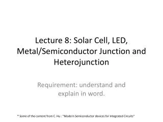
Lecture 8: Solar Cell, LED, Metal/Semiconductor Junction and Heterojunction. Requirement: understand and explain in word. * Some of the content from C. Hu : “Modern Semiconductor devices for Integrated Circuits”. 5.7 Solar Cells. Solar Cells is also known as photovoltaic cells .

E N D
Lecture 8: Solar Cell, LED, Metal/Semiconductor Junction and Heterojunction Requirement: understand and explain in word. * Some of the content from C. Hu : “Modern Semiconductor devices for Integrated Circuits”
5.7 Solar Cells • Solar Cells is also known asphotovoltaic cells. • Converts sunlight to electricity with 10-30% conversion efficiency. • 1 m2 solar cell generate about 150 W peak or 25 W continuous power. • Low cost and high efficiency are needed for wide deployment.
Short Circuit I Dark IV light N Eq.(4.9.4) P I 0.7 V sc - 0 V E Solar Cell c IV Eq.(4.12.1) Maximum E – I power-output v sc + (a) Solar Cell Basics
Direct-Gap and Indirect-Gap Semiconductors direct-gap semiconductor indirect-gap semiconductor • Electrons have both particle and wave properties. • An electron has energy E and wave vector k. Direct-gap semiconductor: Absorption coefficient is larger . Si is most prevalent for solar cell because of low cost.
Light Absorption α(1/cm): absorption coefficient 1/α: light penetration depth A thinner layer of direct-gap semiconductor can absorb most of solar radiation than indirect-gap semiconductor. Si solar cell > 50 um in thickness to absorb most of the photons because of low α
Short-Circuit Current and Open-Circuit Voltage If light shines on the N-type semiconductor and generates holes (and electrons) at the rate of G s-1cm-3 , If the sample is uniform (no PN junction), d2p’/dx2 = 0 p’ = GLp2/Dp= Gtp
Solar Cell Short-Circuit Current, Isc Assume very thin P+ layer and carrier generation in N region only. G is really not uniform. Lp needs be larger than the light penetration depth to collect most of the generated carriers.
Open-Circuit Voltage • Total current is ISC plus the PV diode (dark) current: • Solve for the open-circuit voltage (Voc) bysetting I=0 How to raise Voc ?
A particular operating point on the solar cell I-V curve maximizes the output power (I V). Output Power • Si solar cell with 15-20% efficiency dominates the market now • Theoretically, the highest efficiency (~24%) can be obtained with 1.9eV >Eg>1.2eV. Larger Eg lead to too low Isc (low light absorption); smaller Eg leads to too low Voc. • Tandem solar cells gets 35% efficiency using large and small Eg materials tailored to the short and long wavelength solar light.
NRL’s new triple-junction solar cells could achieve 50 percent efficiency
Ec Non-radiative recombination through traps Radiative recombination Ev 5.8 Light Emitting Diodes and Solid-State Lighting • Light emitting diodes (LEDs) • LEDs are made of compound semiconductors such as InP and GaN. • Light is emitted when electron and hole undergoradiative recombination.
Direct and Indirect Band Gap Trap Indirect band gap Example: Si Direct recombination is rare as k conservation is not satisfied Direct band gap Example: GaAs Direct recombination is efficient as k conservation is satisfied.
LED Materials and Structure compound semiconductors binary semiconductors: - Ex: GaAs, efficient emitter ternary semiconductor : - Ex: GaAs1-xPx , tunable Eg (to vary the color) quaternary semiconductors: - Ex: AlInGaP , tunable Eg and lattice constant (for growing high quality epitaxial films on inexpensive substrates) Eg(eV) red yellow blue Red Yellow Green Blue Light-emitting diode materials
AlInGaP Quantun Well Common LEDs
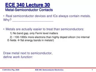
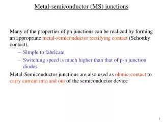
5.9 Metal-Semiconductor Junction • Two kinds of metal-semiconductor contacts: • Rectifying Schottky diodes:metal on lightly doped silicon • Low-resistance ohmic contacts: metal on heavily doped silicon
Vacuum level, E 0 = 4.05 eV c c Si Si q y y M M q f E Bn c E f E v fBn Increases with Increasing Metal Work Function : Work Function of metal : Electron Affinity of Si Theoretically, fBn= yM – cSi
Depletion Metal Neutral region layer qfBn Ec Ef N-Si Ev Ec P-Si Ef Ev qfBp SchottkyBarriers Energy Band Diagram of Schottky Contact • Schottky barrier height, fB, is a function of the metal material. • fB is the most important parameter. The sum of qfBn and qfBp is equal to Eg .
Schottky barrier heights for electrons and holes fBn + fBp Eg fBnincreases with increasing metal work function
Vacuum level, E 0 c = 4.05 eV Si q y M q f E Bn c + - E f E v Fermi Level Pinning (Schottky barrier lowering) • A high density of energy states in the bandgap at the metal-semiconductor interface pins Ef to a narrow range and fBn is typically 0.4 to 0.9 V • Question: What is the typical range of fBp?
qfbi qfBn Ec Ef Ev qfBn q(fbi + V) qV Ec Ef Ev Using C-V Data to Determine fB Question: How should we plot the CV data to extract fbi?
qfbi 2 qfBn 1 /C Ec Ef Ev V - f bi Using CV Data to Determine fB Oncefbi is known, fB can be determined using
Thermionic Emission Theory v thx - E q( f - V) B c q f N-type B E qV E fn V Metal Silicon fm E v x
Forward biased V = 0 I V Reverse bias Forward bias Reverse biased SchottkyDiodes
I Schottky Schottky diode I f f PN junction PN junction B B diode V V Applications of Schottly Diodes • I0 of a Schottky diode is 103 to 108 times larger than a PN junction diode, depending on fB .A larger I0 means a smaller forward drop V. • A Schottky diode is the preferred rectifier in low voltage, high current applications.
5.10 Heterojunction Heterojunction gives us additional parameters to manipulate the ratio of electron/hole current More will be discussed in ECE684: HEMT
What is the energy band diagram at thermal equilibrium? What is Vbi