HDLC
HDLC. High-Level Data Link Control ( HDLC ) is a bit-oriented code-transparent synchronous data link layer protocol developed by the International Organization for Standardization (ISO). Most important data link control protocol. From where it started???.

HDLC
E N D
Presentation Transcript
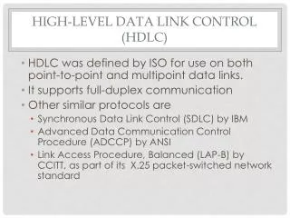
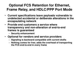
HDLC • High-Level Data Link Control (HDLC) is a bit-oriented code-transparent synchronous data link layer protocol developed by the International Organization for Standardization (ISO). • Most important data link control protocol.
From where it started??? • Synchronous Data Link Control (SDLC) by IBM • Advanced Data Communication Control Procedure (ADCCP) by ANSI
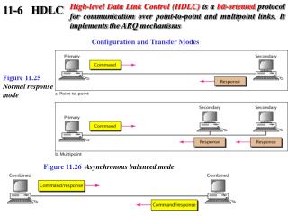
Basic Characteristics • Primary station • Responsible for controlling the operation of the link. • Handles error recovery • Frames issued by the primary station are called commands. • Secondary station • Operates under the control of the primary station. • Frames issued by a secondary station are called responses. • The primary station maintains a separate logical link with each secondary station. • Combined station • Combine the features of both primary and secondary station.
Two Link Configurations Unbalanced Mode Commands Primary Responses Secondary Secondary Balanced mode Combined Combined commands/Responses
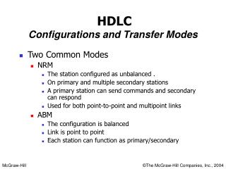
Three Data Transfer Modes • Normal Response Mode (NRM) • Used with an unbalanced configuration. • Primary may initiate data transfer to secondary. • But secondary may only transmit data in response to a command from a primary. • NRM is used on multidrop lines. • Asynchronous Balanced Mode(ABM) • Used with balanced configuration. • Either combined station may initiate transmission without receiving permission from the other combined station. • Widely used, efficient used to connect from one device from one another. • Asynchronous Response Mode(ARM) • Used with an unbalanced configuration. • The secondary may initiate transmission without permission of the primary.
FLAG FIELD: -Frame contains unique pattern at both ends. -No assurance of occurrence of same bit pattern somewhere inside the frame. -Bit Stuffing is used. Original Pattern: 111111111111011111101111110 After bit-stuffing: 1111101111101101111101011111010 • ADDRESS FIELD: -Identify the secondary station that transmitted or is to received the frame.
CONTROL FIELD: The first one or two bits are used to identify the type of frame. Defines three types of frames:- -INFORMATION FRAME(I-FRAME) -Carry data to be transmitted for the user. -Flow and error control data, using the ARQ mechanism, are piggybacked on an I-Frame. -SUPERVISORY FRAME(S-FRAME) -Used for flow and error control whenever piggybacking is impossible -UNNNUMBERED FRAME(U-FRAME) -Used for link management, and can also be used to transfer user data. -They exchange session management and control information between connected devices.
All of the control field contain poll/final (P/F) bit. • It is called Poll when set by the primary station to obtain a response from a secondary station. • Final when set by the secondary station to indicate a response or the end of transmission. In all other cases, the bit is clear.
There are four different supervisory frames: • Receive Ready (RR) Bit Value = 00 Indicate that the sender is ready to receive more data. • Receive Not Ready (RNR) Bit value = 01 Acknowledge some packets and request no more be sent until further notice. • Reject (REJ) Bit value = 10 Requests immediate retransmission starting with N(R). • Selective Reject (SREJ) Bit value = 11 Requests retransmission of only the frame N(R). • FRAME CHECK SEQUENCE FIELD: -Error detecting code calculated from the remaining bits of the frame and exclusive of flags.
THANK YOU.. MY BLOG ID: Anamikasirohi89.wordpress.com