Chapter 19
Chapter 19. Springs. Chapter 19: Springs. Springs Characterized By: Ability to deform significantly without failure Ability to store/release PE over large deflections Provides an elastic force for useful purpose. Chapter 19: Springs. How used in mechanical design?

Chapter 19
E N D
Presentation Transcript
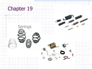
Chapter 19 Springs
Chapter 19: Springs • Springs Characterized By: • Ability to deform significantly without failure • Ability to store/release PE over large deflections • Provides an elastic force for useful purpose
Chapter 19: Springs • How used in mechanical design? • Shock/Vibration protection • Store/Release PE • Offer resisting force or reaction force for mechanism • Example: • Valve spring pushes rocker arm so lifter follows cam • VCR lid – torsion springs keeps door closed
Chapter 19: Springs • Our focus will be on Helical Compression Springs • Standard round wire wrapped into cylinder, usually constant pitch • We will cover design process and analysis
Chapter 19: Springs - Terminology ID –inside diameter of helix OD – outside diameter of helix Dm – mean diameter of helix Lf – free length Ls – solid length Li – installed length Lo – operating length Ff – zero force Fs – solid force Fi – min. operating force Fo – max. operating force Helical Compression Springs:
Chapter 19: Springs - Terminology k – spring rate C – spring index = Dm/Dw N – number of coils Na– number of active coils (careful Na may be different from N – depends on end condition – see slide 9) p – pitch λ– pitch angle cc – coils clearance K – Wahl factor f – linear deflection G – shear modulus t–torsional shear stress to – stress under operation ts– stress at solid length td– design stress
Chapter 19: Springs – Analysis Process: Key Equations: Determine: K, τo, τs to determine if OK for your application 1.) Calc spring rate : 2.) Based on geometry: C = spring index = Dm/Dw Shear mod table 19-4 Wire dia. Table 19-2 **Need to know k to get spring forces to get spring stresses** 3.) Shear stress in spring: (accounts for curvature of spring) Show slide **Compare τo & τs to material allowable (Figure 19-8 – 19-13)**
Chapter 19: Springs – Analysis Process: 4) Buckling Analysis – usually final analysis done to make sure there’s no stability issue. If so, may be as simple as supporting the spring through id or od • Calculate Lf/Dm • From Fig 19-15, get fo/Lf • fo = buckling deflection – you want your maximum deflection to be less than this!! Buckling procedure
2 Categores: Spring Analysis – spring already exists – verify design requirements are met (namely, stiffness, buckling and stress is acceptable) Spring Design – design spring from scratch – involves iterations!!
Spring Analysis Example: Given: Spring- 34ga Music Wire Dm = 1.0 “ Lf = 3.0” Li = 2.5” Lo = 2.0” Na = 15 (squared and ground end) Find: Spring rate, τo, τs Dw = .100” (table 19-2)
Spring Analysis Example: Fo = k ΔL = 9.875 lb/in (1 in) = 9.875 lb Lf - Lo 3” – 2” operating force o IS this stress ok? See figure 19-9 (severe or average service)
Spring Analysis Example: Squared and ground (Max force) IS this stress ok? See figure 19-9 (light service since only happens once!!) CHECK FOR BUCKLING!!!
Spring Design Example: Generally all that’s given based on application!! Given: Lo = 2.0 in Fo = 90lb Li = 2.5 in Fi = 30 lb Severe service Find: Suitable compression spring Looks OK compared to ~ 3 in. length
Spring Design Example: Guess: Dm = .75 in. Try: Cr – Si Alloy, A-401 Guess: τallow = 115 ksi (Figure 19-12) o Try: 11 gage = .1205 in. (Table 19-2)
Spring Design Example: FROM APPENDIX 19-5: τsevere allow = 122 ksi (operating max.) τlight allow = 177 ksi (solid max.) ( > 5, so OK )
Spring Design Example: OK < 122 ksi o
Spring Design Example: (squared and ground ends assumed) 294 ksi > 177 ksi - WILL YIELD, NOT ACCEPTABLE
Spring Design Example: How to check buckling: Critical ratio = ? For any fo/Lf This spring is below fixed end line and fixed-pinned. If pinned-pinned critical ratio = .23 .273 > .23: So it would buckle
Spring Design Example: Trials Select one of these
Side Info: How determine initial estimate for Dw Equation for shear stress where geometry is known But…. Τallow and K depend on Dw So……Guess K is mid-range, about 1.2 Then: Re-arrange…. This Dw is about where to start for spring design. Both K and τallow may be found for selected Dw.