Stored Program Architecture
Stored Program Architecture. Lecture 9. The von-Neumann Architecture. Stored Program Concept - Storing instructions in memory along with data Memory Processor - CPU Input/Output devices. I/O. input/output devices enable the user to interact with the computer


Stored Program Architecture
E N D
Presentation Transcript
Stored Program Architecture Lecture 9
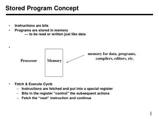
The von-Neumann Architecture • Stored Program Concept - Storing instructions in memory along with data • Memory • Processor - CPU • Input/Output devices
I/O • input/output devices enable the user to interact with the computer • input devices – keyboards, mice, scanners, … • output devices – display screens, speakers, printers, …
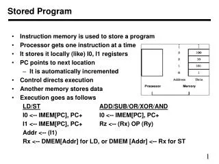
Main Memory • Main memory is a large number of memory locations. Each location is accessible via an address. It holds: • Data • Active programs - instructions for the CPU. Storing the instructions for the cpu in memory called the stored program concept (Von Neumann) . Program isstored in the machine language (binary) that corresponds to the circuitry of that processor.
Memory • Programmer writes a program in a high level language that is easy to understand, like Java, C++ or JavaScript. • Program is translated into machine language by a compiler or interpreter. • The binary code is stored in the main memory along with the data.
CPU – Central Processing Unit • ALU - arithmetic/logic unit circuitry for arithmetic and logic operations (e.g. addition, comparison, OR) • CU - control unit • fetches instructions from memory • decodes the instruction • executes the instruction • registers – • memory locations built into the CPU (to provide fast access) • hold data for immediate use by ALU
Bus • Just like it sounds. What does a bus do? • Busesare circuits over which data travels • Buses connect parts of the the CPU and main memory • Takes time to get data from main memory, so it’s slower than registers.
CPU • CPU acts as the brain of the computer • it fetches data and instructions from memory • it executes the instructions • it stores results back to memory • (Be patient for a few slides)
Control Unit • The control unit • fetches instructions from memory • decodes the instruction • executes the instruction • The control unit has two important registers: • PC-program counter - contains the address in main memory of the next instruction • IR-instruction register - holds the instruction thatis currently executing
Machine cycle • Thecontrolunit • fetches from main memory the instruction whose address is in the program counter. The instruction is stored in the instruction register and the program counter is incremented to the next instruction address. • decodes the instruction to understand what needs to be done. • executesthe instruction by performing the operation on the data.
The above three steps are repeated until the end of the stored program. • A computer can execute millions of instructions per second.
Example • S’pose the control unit is executing an instruction to add two numbers: • obtain first value from memory and store in a register • obtain second value from memory and store in a register • use the addition circuitry to add the two numbers in the registers and place the result in a register • store the result in main memory
HW • Please read chap 14 and bring book to class for lab 9 • The next few slides are preparation for the lab. They are a continuation of the Addition Example
Assembly language • 0: LOAD R0 5 // R0 = M[5] • 1: LOAD R1 6 // R1 = M[6] • 2: ADD R2 R0 R1 // R2 = R0 + R1 • 3: STORE 7 R2 // M[7] = R2 • 4: HALT // HALT • 5: 9 // 9 data value • 6: 1 // 1 data value • 7: 0 // will hold result
Machine Language (no spaces) • 0: 100000010 00 00101 // R0 = M[5] • 1: 100000010 01 00110 // R1 = M[6] • 2: 1010000100 10 00 01 // R2 = R0 + R1 • 3: 100000100 10 00111 // M[7] = R2 • 4: 1111111111111111 // HALT • 5: 0000000000001001 // 9 data value • 6: 0000000000000001 // 1 data value • 7: 0000000000000000 // will hold result
Simulator Machine Language • 1st two instructions – select ALU operation and registers to operate on • next 3 instructions – control flow of data. Store should be location 5. • last instruction – marks the end of instruction sequence
Program Execution • example: machine language program for adding two numbers in memory • program execution: • program counter is initialized: PC = 0 • instruction at memory location 0 is fetched, PC is incremented to 1 • instruction is decoded and CPU cycle is executed: load contents of memory location 5 into RO • next instruction is fetched at location 1, PC is incremented to 2 • instruction is decoded and CPU cycle is executed: load contents of memory location 6 into R1 • next instruction at memory location 2 is fetched, PC is incremented to 3 • instruction is decoded and CPU cycle is executed: add contents of R0 and R1, store result in R2 • next instruction at location 3 is fetched, PC is incremented to 4 • instruction is decoded and CPU cycle is executed: copy contents of R2 into memory location 7 • next instruction at location 4 is fetched, PC is incremented to 5 • instruction is decoded and CPU cycle is executed: halt instruction program ends