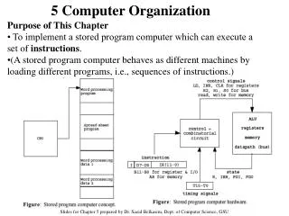
Computer Implementation: Component Parts and Internal Structure
Understand the internal structure and component parts of a stored program computer including processor, memory, input/output circuits, and buses.

Computer Implementation: Component Parts and Internal Structure
E N D
Presentation Transcript
Implementation of a Stored Program Computer ITCS 3181 Logic and Computer Systems 2014 B. Wilkinson Slides2.ppt Modification date: March 3, 2014
Component Parts of a Stored Program Computer • Consists of: • Processor • Memory • Input circuits and devices • Output circuits and devices • Input devices (such as a keyboard) used to enter information. • Output devices (such as a printer) used to obtain results from the computer.
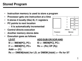
Internal Structure of Computer Input device(s) Output devices Input Main Output interface(s) memory interface(s) Bus Instructions (set of wires) and data Processor Note: Recent computers use more than one bus – separate buses for memory etc. Convenient to connect the processor, main memory and I/O connect through a set of common wires called a “bus”:
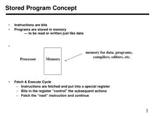
Processor fetches binary encoded machine instructions from memory and performs actions defined, for example, add two numbers together and put result back in memory.
Main memory • Set of storage locations holding binary patterns. • Used to hold: • Machine instructions • Data • Each location given a unique address (a binary number starting from zero). • Each “addressable” location holds a fixed number of bits. • Any location can be accessed at high speed in any order (random access memory).
Size of memory locations In the early days of computers (and perhaps up to 1970), each manufacturer decided on how many bits would be in each memory location. Various sizes existed e.g. 24 bits, 36 bits, 40 bits, etc. Usually dictated by the number of bits in the instruction. Also defined the number of bits in numbers stored in memory. Currently (and for last 30 years at least), each addressable memory location holds 8 bits (a byte) Originally convenient for holding ASCII (American Standard Code for Information Interchange) code that represented alphanumeric characters (letters, digits, symbols as found on a keyboard), i.e. char data type in a high level language, e.g. char x; More recently Unicode/UTF-8 variable width encoding (1 - 4 bytes) encoding mostly used - Encodes most of characters used in world (ASCII a subset). See www.unicode.org/, en.wikipedia.org/wiki/UTF-8
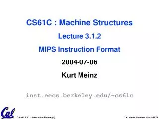
Size of memory locations continued 8 bits is not suitable for machine instructions, each of which typically would need more than 8 bits, or for numbers.For more than 8 bits, consecutive locations used. Address given by address of first location. Example 32-bit integer variables a, b, c, and d might be located at addresses 0, 4, 8, 12. First location holds least significant byte first, Little Endian (little end) or most significant byte first, Big Endian (big end) depending upon convention of processor: Big endian – early common approach Found in some current processors Sometimes selectable Used in network protocols Intel uses little endian (a little easier logic) Gulliver’s Travels
Little endian (little end first) Big endian (big end first)
Question Suppose a compiler uses the memory locations starting from location zero to hold the variable x using big endian representation. Specify what would be in these memory locations (in binary) if the program has the statement: int x = 17; The memory is byte-addressable (each location holding a byte) and x is a 32-bit number. Answer
Follow-on question Suppose x is then read from memory by a processor using little endian representation. What value would it get? Answer
Bytes, half word, words, double words and all that • Many processors support multiple data sizes: • High level language • declaration of variable x • 8 bits byte byte x;(Java ) char x; (C) • 16 bits half words • 32 bits words intx; • 64 bits double words long int x; • Size of data needs to be selected. • Other formats also see later.
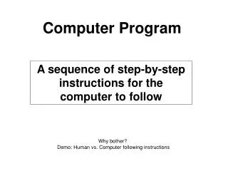
Machine Instructions The operation of an instruction reduced to a very simple form. Consider a calculation one might write in a high level language: x = (y + z) / (a - b); where a, b, x, y, and z are declared as integers. Unreasonable to provide a specific machine instruction just for this calculation. Need to break down calculation into a series of simple arithmetic operations.
Suppose the variables a, b, x, y, and z are stored by the compiler in memory locations 100, 104, 108, 112, and 116: temp1 = y + z temp2 = a - b x = temp1/temp2 temp1, temp2 could be memory locations but better to use fast internal register storage, see later. Note: integers are stored in registers by the compiler if possible
Machine Instructions Each of the steps in the previous example: temp1 = y + z temp2 = a - b x = temp1/temp2 might be encoded into one machine instruction. Each machine instruction usually only has one operation (+, - etc), possibly two source operands, and a single result.
Machine Instruction Encoding A binary pattern that specifies one operation (usually), the operands used for the operation and where the result should be placed if any.
Op-code Encoding Suppose there were 60 different operations, add subtract, multiply, divide, etc. Six bits would be sufficient (25 <= 60 <26). Could allocate one pattern for each operation: Example op-code ADD (“ADD”) 000001 SUBTRACT (“SUB”) 000010 MULTIPLY (“MUL”) 000011 DIVIDE (“DIV”) 000100 . . Sometimes more complex encoding used. Many possibilities. Pattern of all zeros often reserved for no operation (“no-op”)
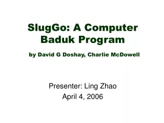
Specifying the Locations of Operands First let us assume operands and results in main memory: Three-Address Format Note Order of operands here is with destination first but it could be different depending upon processor.
Example: Addition
Machine Instruction The processor executes machine instructions which are binary patterns. The previous machine instruction might be encoded as: where in this case, 6 bits in opcodeand 32 bits for each address.
Assembly Language and Machine Instructions Much more convenient to use an “assembly language” notation to describe machine instruction rather than actual binary patterns. Previous machine instruction might be written in assembly language as: ADD [300], [200], [100] where [] means “contents of memory”, a common notation. ADD is the op-code mnemonic.
The 3-(memory) address format has the disadvantages: • Long instruction length • Three memory accesses • and rarely used.
Two-Address Format Operands and results in memory. One operand and result same location Eliminates one address
Example: ADD [200], [100]
Disadvantages: • One operand overwritten • Still needs three memory accesses
One-Address Format Only one location allowed for one operand and result, a location within the processor, called an accumulator historically. Other operand still in main memory, and its address given in instruction:
Example ADD [100]
Advantages: • Shorter instruction • Eliminates two memory accesses • Faster accessing location inside processor than memory • Disadvantages: • Only one location for one operand and result • Still needs one memory access
Register Format Have more than one location within processor - set of registers. If there were 32 registers, say R0 to R31, 5 bits are required in each field to specify the register.
Example ADD R1, [100]
Register-Register Formats With registers, can now hold all operands in registers and operate on registers only: If 2 registers specified If 3 registers specified
Example ADD R3,R1,R2
Zero-Address Format Possible to eliminate all addresses by using specific locations. Then only the operation need be specified in the instruction Usually locations for operands/result are top two locations of a stack (a last-in first-out queue) in memory or implemented with registers within processor. Stack pointer - a register within processor used to hold the address of the top location.
Example ADD Zero-address format useful to compilers for producing code for arithmetic expressions (using reverse Polish notation) Used by Burroughs in their computers in the 1960’s and not widely since (but re-introduced in SUN Java chip).
We have outlined several instruction format possibilities: • 3-address • 2-address • 1-address • register formats (3 register or 2 register) • zero-address • A particular processor will not use all formats.
Examples Intel 64/IA-32 instruction set processors (continuing early 8086 processor designs) - 2-address formats with one operand in a register, the other in a register or memory. IBM PowerPC, SUN Sparc processor (and other so-called reduced instruction set computers) - 3-register format for arithmetic and register-memory format for accessing memory operands. More details later.
Quiz 1. How many references to memory are needed for each of the following hypothetical instructions? ADD [100],[100],[100] ADD [100],[100],R2 2. Why are registers used in a processor?
Quiz 3. Write a suitable assembly language sequence for the following high level language statement: z = (x *(y - z)) - z; assuming a processor with 32 registers R0 to R31 with the variables x, y, and z stored in R1, R2, and R3 respectively.