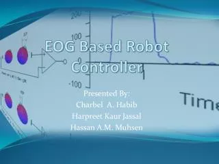
EOG Based Robot Controller
EOG Based Robot Controller. Presented By: Charbel A. Habib Harpreet Kaur Jassal Hassan A.M. Muhsen. Outline. The Project Input unit Processing unit Control Unit Output unit Future Work Conclusion. The Project System Architecture. EOG. EOG Signal EOG: Electrooculogram

EOG Based Robot Controller
E N D
Presentation Transcript
EOG Based Robot Controller Presented By: Charbel A. Habib Harpreet Kaur Jassal Hassan A.M. Muhsen
Outline • The Project • Input unit • Processing unit • Control Unit • Output unit • Future Work • Conclusion
EOG • EOG Signal • EOG: Electrooculogram • the recording of the changes in voltage that occur with the eye position. • Electro: electrical • Oculo: eye • Gram: recording
EOG • EOG Signal • EOG: Electrooculogram • spherical battery • positive terminal: the cornea • negative terminal: the retina. • 0.4 and 1 mV
EOG • EOG Signal
EOG • EOG Signal • The signals are measured using EEG disposable electrodes
Input Unit • Sensors • Amplifier
EOG • Electrode signal: • 0.4 and 1 mV • This low voltage is not strong neither usable SOLUTION: ???
EOG • Amplifier • Designing an amplifier • Requirements: • Total gain of 5000 • Cutoff frequency of 25Hz LPF • Offset compensation
Difference Amplifier Amplifier Gain = -R2/R1
High Frequency Filter 4th order Butterworth Filter Cut off Frequency of Filter (f0)= 1/(2π*R*C)
Inverting and Non inverting Amplifier + Rectifier Inverting Amplifier = -R2/R1 & Non Inverting Amplifier = 1+ R2/R1
Problems • Unavailability of small power supply • Electrodes • Amplifier Vcc supplier
Main Unit • Process Unit • Control Unit
Right side movement of eyes Movement of eyes during reading Left side movement of eyes Upside movement of eyes Blinking movement of eyes Downward movement of eyes Processing Unit
Signal Processing Filtering (Median Filter) Segmentation (Clustering)
Problems • Microcontroller Delay • Median Filter Window Size
Control Unit • Translation (PWM) • Center = 128 • Right & Up = 185 • Left & Down = 70 • Communication • Direct from Microcontroller
Main Unit • Overall Picture
Problems • Calibration • ADC Delay
Future Work • On/Off Mechanism • Real Neck Implementation • Applying to Aesop3000
THANKS Any Questions???