Serial Peripheral Interface (SPI)
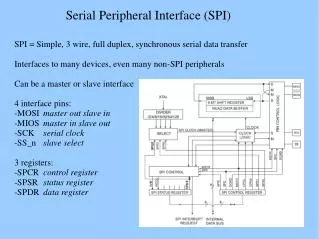
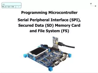
Serial Peripheral Interface (SPI). Functions. SPI allows high-speed synchronous data transfer between ATmega128 and peripheral devices or between several AVR devices . Features. Full-duplex, Three-wire Synchronous Data Transfer Master or Slave Operation LSB First or MSB First Data Transfer

Serial Peripheral Interface (SPI)
E N D
Presentation Transcript
Functions • SPI allows high-speed synchronous data transfer between ATmega128 and peripheral devices or between several AVRdevices
Features • Full-duplex, Three-wire Synchronous Data Transfer • Master or Slave Operation • LSB First or MSB First Data Transfer • Seven Programmable Bit Rates • End of Transmission Interrupt Flag • Write Collision Flag Protection • Wake-up from Idle Mode • Double Speed Master SPI Mode
Interconnection system consists of two shift registers and a master clock generator • Procedure of data communication • SPI Master sets Slave Select SS/ pin to low • Master and Slave prepare the data to be sent in their respective shift registers • Master generates the clock pulses on the SCK line to interchange data • Data is shifted from Master to Slave on the Master Out – Slave In (MOSI) line, and from Slave to Master on the Master In – Slave Out (MISO) line • After each data packet is transmitted, the Master sets SS/ to high for synch with Slave
Registers • SPI Control register – SPCR • Bit 7 (SPIE) : SPI Interrupt Enable • Bit 6 (SPE) : SPI Enable • Bit 5 (DORD) : Data Order. When DORD = 1, LSB of data word is transmitted first When DORD = 0, MSB of data word is transmitted first
Bit 4 (MSTR) : Master/Slave Select If MSTR = 1, Master SPI mode. If MSTR = 0, Slave SPI mode • Bit 3 (CPOL) : Clock Polarity If set to 0, SCK is high when idle If set to 1, SCK is low when idle • Bit 2 (CPHA) : Clock Phase – determines whether data is sampled on the leading (first) or trailing (last) edge of SCK
SPI Status Register (SPSR) • Bit 7 (SPIF) : SPI Interrupt flag • Bit 6 (WCOL) : Write COLlision flag -- WCOL is set if SPDR is written during a data transfer (collision occurred) • Bit 0 (SPI2X) : Double SPI Speed bit -- when this bit is set to 1, SPI speed (SCK frequency) will be doubled when SPI is in Master mode
SPI Data Register (SPDR) • Writing to SPDR initiates data transmission • Reading SPDR causes the Shift Register Receive buffer to be read
[Ex] Initialize the SPC as a Master and perform a simple transmission
[Ex] Initialize the SPC as a Slave and perform a simple reception