SPI - Serial Peripheral Interface
SPI - Serial Peripheral Interface. Pour aller lire le CAN et écrire dans le CNA. Schéma bloc. Registre des modes du SPI. Exemple initialisation du SPI. Configuration du SPI. 1) Associer les broches au SPI: Exemple SPI #1: PIO_Configure (pinsSPI1 , PIO_LISTSIZE(pinsSPI1 ));.

SPI - Serial Peripheral Interface
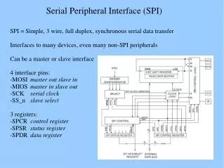
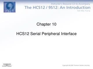
E N D
Presentation Transcript
SPI - Serial Peripheral Interface Pour aller lire le CAN et écrire dans le CNA
Configuration du SPI • 1) Associer les broches au SPI: • Exemple SPI #1: • PIO_Configure(pinsSPI1, PIO_LISTSIZE(pinsSPI1));
Configuration du SPI • 2) Configuration du registre AAAA: • Structure: • config = (AT91C_SPI_DLYBCS & (0 << 24)) | • (AT91C_SPI_PCS & (0xE << 16)) | • (AT91C_SPI_LLB & (0 << 7)) | • (AT91C_SPI_MODFDIS & (1 << 4)) | • (AT91C_SPI_PCSDEC & (0 << 2)) | • (AT91C_SPI_PS & (1 << 1)) | • (AT91C_SPI_MSTR & (1 << 0)); • SPI_Configure(AT91C_BASE_SPI1, AT91C_ID_SPI1, config);
Configuration du SPI • 2) Configuration du registre AAAA: • Structure: • config = (AT91C_SPI_DLYBCS & (0 << 24)) | • (AT91C_SPI_PCS & (0xE << 16)) | • (AT91C_SPI_LLB & (0 << 7)) | • (AT91C_SPI_MODFDIS & (1 << 4)) | • (AT91C_SPI_PCSDEC & (0 << 2)) | • (AT91C_SPI_PS & (1 << 1)) | • (AT91C_SPI_MSTR & (1 << 0)); • SPI_Configure(AT91C_BASE_SPI1, AT91C_ID_SPI1, config); Délais entre « chip select » « Chip select » périphérique « Local loopback » Détection de fautes Décodage périphérique Sélection périphérique comm. Maitre ou esclave
Configuration du SPI • 2) Configuration du registre AAAA: • Structure: • config = (AT91C_SPI_DLYBCT & (0x01 << 24)) | • (AT91C_SPI_DLYBS & (0x01 << 16)) | • (AT91C_SPI_SCBR & (0x10 << 8)) | • (AT91C_SPI_BITS & (AT91C_SPI_BITS_16)) | • (AT91C_SPI_CSAAT & (0x0 << 3)) | • (AT91C_SPI_NCPHA & (0x0 << 1)) | • (AT91C_SPI_CPOL & (0x1 << 0)); • SPI_ConfigureNPCS(AT91C_BASE_SPI1, 3, config); • SPI_ConfigureNPCS(AT91C_BASE_SPI1, 2, config);
Configuration du SPI • 2) Configuration du registre AAAA: • Structure: • config = (AT91C_SPI_DLYBCT & (0x01 << 24)) | • (AT91C_SPI_DLYBS & (0x01 << 16)) | • (AT91C_SPI_SCBR & (0x10 << 8)) | • (AT91C_SPI_BITS & (AT91C_SPI_BITS_16)) | • (AT91C_SPI_CSAAT & (0x0 << 3)) | • (AT91C_SPI_NCPHA & (0x0 << 1)) | • (AT91C_SPI_CPOL & (0x1 << 0)); • SPI_ConfigureNPCS(AT91C_BASE_SPI1, 3, config); • SPI_ConfigureNPCS(AT91C_BASE_SPI1, 2, config); Délai entre 2 transactions Délai avant SPCK Vitesse communication Taille du transfert (16 bits) Chip select actif après trans. ? Phase de l’horloge Polarité de l’horloge du SPI CNA CAN
Configuration du SPI • 3) Activation du SPI: • Directement (pour le SPI #1): • SPI_Enable(AT91C_BASE_SPI1); • Tout cela peut se regrouper dans une fonction que nous pouvons nommer: • voidinitSPI(void){ • … • }
Configuration broches MAX5322 Déclaration variables SetupDAC() Board.h
Suite Broche LDAC mise à 1 Broche CLR mise à 1 Broche UNI/BIP A mise à 0 Broche UNI/BIP B mise à 1 Broche SHDN mise à 1
Transactions du SPI avec le CNA • Initialisation du CNA • SPI_Write(AT91C_BASE_SPI1, 3, 0xE000); • SPI_Read(AT91C_BASE_SPI1); • Wait(1000); • SPI_Write(AT91C_BASE_SPI1, 3, (0x4000 | 0x07FF)); • SPI_Read(AT91C_BASE_SPI1); Activations des canaux du CNA 0 volt Canal A – DAC_OUT
Transactions du SPI avec le CNA • Initialisation du CNA • SPI_Write(AT91C_BASE_SPI1, 3, 0xE000); • SPI_Read(AT91C_BASE_SPI1); • Wait(1000); • SPI_Write(AT91C_BASE_SPI1, 3, (0x4000 | 0x07FF)); • SPI_Read(AT91C_BASE_SPI1); • SPI_Write(AT91C_BASE_SPI1, 3, (0x5000 | 0x0000)); • SPI_Read(AT91C_BASE_SPI1); Activations des canaux du CNA 0 volt Canal A – DAC_OUT 0 volt Canal B - VSHIFT
Transaction avec le CAN • Pour une lecture du CAN, il faut faire deux transactions. • La première envoie le numéro du canal à lire; • Exemple: 0x9100 • START = 1 • Canal choisi: 0x001 – Canal 1 • RNG = 1 et BIP = 0: Sortie monopolaire; • PD1 = 0 et PD0 = 0: Opération normale, horloge interne. • Réponse du convertisseur: les 3 premiers bits du CAN.