Download

1 / 17
170 likes | 193 Vues
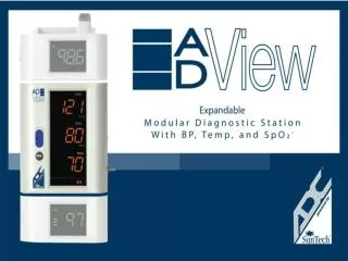
Learn how to add the thermometry module to your ADC Adview diagnostic station. Follow simple steps to connect the module and synchronize it with the device. Enhance your diagnostic capabilities today!

E N D
Adding to your Diagnostic Station
Adding to your ADC Adview You can add functions to your diagnostic station. Click on the module that you want to add • Pulse oximetry • Thermometry Or let us know what modules you would like to have by leaving us feedback at • www.adctoday.com
Adding thermometry The temperature module attaches to the top of the BP module. It is made up of the following two pieces: Display (Part A) Holder/Well (Part B)
Adding thermometry • Using the power button on the right side of the BP module, ensure that the ADC Adview is off. • Remove the cover plate from the top of the BP module.
Adding thermometry • Slide part A of the temperature module along the guides on the top of the BP module from front to back until it snaps into place. All the segments of the temperature module display will light when the modules have been connected correctly. Display (Part A) Holder/Well (Part B) Display (Part A)
Adding thermometry • Attach the temperature probe connector to part B as follows: with the black surface facing downward, hold the probe connector end against the notches on the probe holder, as shown in red.
Adding thermometry • Rotate the connector upwards until it snaps securely into place. The black surface faces outward and the cord extends upward.
Adding thermometry • Slide part B onto part A as shown (this connects the temperature probe connector to the temperature unit connector), and insert the temperature probe into the well. Holder/Well (Part B) Display (Part A)
Synchronizing the modules • Turn the device on using the power button on the right side of the BP module. At the end of the start-up sequence, the temperature module display will blank except for the appropriate temperature unit icon (°F or °C). A short beep indicates that the ADCAdview is ready. Refer to the ADCAdviewuser’s manual for operation, maintenance and safety instructions. Need help?
Changing the unit of temperature measurement Using the end of a paper clip or similar tool, press the recessed button on the temperature module. The icon for the selected unit is displayed.
Adding pulse oximetry The pulse oximetry module attaches to the bottom of the BP module. Included in the Pulse Oximetry Module kit are the pulse oximetry module, the adult reusable sensor, and a 6’ extension cable.
Adding pulse oximetry • Using the power button on the right side of the BP module, ensure that the ADCAdviewis off. • Remove the cover plate from the bottom of the BP module.
Adding pulse oximetry • Slide the pulse oximetry module along the guides on the bottom of the main BP module from front to back until it snaps into place. All the segments of the pulse oximetry module display will light when the modules have been connected correctly.
Adding pulse oximetry • Turn the device on using the power button on the right side of the BP module. At the end of the start-up sequence, the pulse oximetry module display will blank except for the “%SpO2” symbol. • Turn the device off, connect the adult reusable sensor to the 6’ extension cable, and then the cable to the connector on the module. Secure the cable to your device using the retention clip.
Synchronizing the modules • Turn the device on. All display segments light up for three to five seconds. A short beep indicates that the ADCAdview is ready. Refer to the ADCAdview user’s manual for operation, maintenance and safety instructions. Need help?
Need help? Contact us by telephone: • 1.800.232.2670 or 1.631.273.9600 Or by email: • CustomerService@adctoday.com Or find help on the Internet: • www.adctoday.com