
MICE RFCC Module Update
E N D
Presentation Transcript
Steve Virostek Allan DeMello Lawrence Berkeley National Laboratory MICE RFCC ModuleUpdate MICE CM27 at RAL, UK July 8, 2010
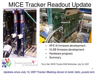
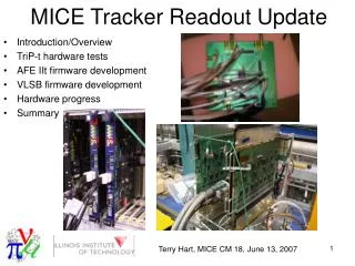
MICE RFCC Module Update Overview • RF cavities • RF cavity frequency tuners • Cavity RF couplers • Beryllium windows • RFCC module schedule
RF Cavity Progress Summary • Completion of second set of five cavities by Applied Fusion expected in September 2010 • Physical (CMM) measurement of first five cavities recently completed • RF frequency and Q measurements of first five cavities recently completed • Local (near LBNL) electro-polishing company has been identified and discussions initiated
RF Cavity Fabricator - Applied Fusion, Inc. • E-beam welding of stiffener rings and equators complete • Port holes are machined and ready for port pulling
RF Cavity Physical Measurement • Physical measurement of the first five cavities using a CMM is complete • Specialized tooling was procured to allow measurement of cavity inner profile • Cavities are ~10 mm narrower than nominal (likely caused by cooling tube brazing), but no issues are expected • Second set of five cavities will be inspected when delivered to LBNL
RF Cavity Frequency Measurement • RF frequency measurements for the first five cavities are complete • The three Be windows at LBNL have also been characterized • Refer to Derun Li’s talk for details
RF Cavity Electropolish Vendor • The inside surface of each RF cavity will be electropolished • Discussions under way with local company Milpitas California (40 mi to LBNL) Electro-polish tank dimensions: 12' Long x 5' Wide x 6' Deep Large SS piping weldment at AET
RF Cavity Future Work • Physical (CMM) and frequency measurements will be performed on the remaining five cavities when they become available • Leak and flow check of the cooling tubes will be performed • The inside surface of each RF cavity will be mechanically buffed and electropolished • The ten cavities will be “tuned” to each other through plastic deformation (if necessary) for best center frequency (to be done at LBNL)
RF Cavity Frequency Tuner Progress • Tuner design is complete • One full size tuning arm (for testing the system) has been fabricated • Aluminum test cylinder (1/6 of cavity) has been fabricated to replicate the cavity stiffness • Assembly of a pneumatic actuator has been completed • Control system components have been assembled into a working system • Integrated tuner system has been tested, and ±2 mm of tuner arm motion has been confirmed
RF Cavity Frequency Tuner Overview • 24 dynamic cavity frequency tuners per module • Tuner Actuator • Tuner Flexure Arm • Tuners operate in a bi-directional “push - pull” mode (±2 mm) • Tuning will be automatically achieved through a frequency feedback loop
RF Cavity Frequency Tuner Components • Tuner/actuators are thermally independent of the vacuum vessel • Dual–action actuator • Actuator is • screwed into • the tuner arm • Flexure • tuner arm • Fixed • connection to cavity
Prototype Actuator Design • Dual–action (push/pull) actuator • Actuator mechanical components (except bellows) were fabricated and assembled at LBNL • Forces are transmitted to the cavity stiffener ring by means of “push-pull” loads applied to the tuner flexure arms by the dual action actuator assembly
Tuner System Analysis Review • The Von Mises stress at the flexure is 205 Mpa (30 ksi) • The input load by the air actuator is 3.56 kN (800 lb) • The tuner arm displacement is 5.4 mm (10.9 mm bi-directional) • The cavity displacement is 1.0 mm per side
Tuner Flexure and Test Ring • Full size (3” thick stainless steel) prototype tuner flexure with actuator and test ring • Prototype actuator threaded into tuner arm • Aluminum test ring with spring rate equivalent to 1/6th of a cavity
Prototype Tuner Arm Test Setup Test set-up includes: 1. Actuator, tuner arm and test ring 2. Control regulators and manifolds 3. Computer control
RF Cavity Tuner Control System • Emerson ER3000 electronic pressure controllers – one for each side of the actuator • ±0.1% accuracy (over 110 psi range) • Remote computer controlled for frequency feedback • 16 total modules required for two RFCC modules
RF Cavity and Frequency Tuner • Prototype tuner/actuator mounted on cavity
RF Cavity Frequency Tuner Future Work • Order parts for 5 more (6 total) actuators (incorporating any refinements from the prototype) • Fabricate 5 more tuner flexures • Build a cavity suspension frame • Test the RF tuning system with 6 tuners and actuators on a cavity • Actuators will be manifolded together • Frequency measurements will be taken to verify the frequency tuning range
Toshiba RF Window for Cavity RF Coupler • Assembly drawing of cavity RF coupler showing Toshiba RF Window
Toshiba RF Window • Quote for 10 Toshiba RF windows has been obtained • U. Miss. Is in the process of placing the order (~$180k) • Slight modification to SNS design (now all metric threads)
Beryllium Window Update • 3 of 11 windows have been received by LBNL from Brush-Wellman • Windows have been characterized during cavity frequency measurements • An additional 8 windows are expected to be delivered in the next two months