Download
1 / 28
280 likes | 308 Vues
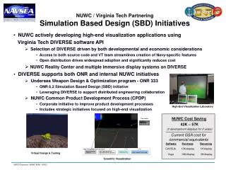
Explore how Raytheon Missile Systems utilizes Modeling and Simulation (M&S) for various operations, design, and testing processes. Learn about the evolution towards a common simulation process and the benefits it brings. Discover the Simulation Framework at RMS and its impact on system design, integration, and testing efforts.

E N D
Towards Simulation Based Acquisition: RMS Initiatives Louisa Guise Sr. Manager Systems Engineer Raytheon Missile Systems, Tucson, Arizona
Simulation at Raytheon Missile Systems • RMS uses Modeling and Simulation (M&S) for operations analysis, proposal support, engineering design, integration & test and performance analysis. • Types of M&S include constructive, virtual and live. • Constructive simulations include • Missile 6 Degree of Freedom (6DOF) or Integrated Flight Simulation (IFS) • Computer-in-the-Loop (CIL) simulations • Hardware-in-the-Loop (HWIL) simulations • System-in-the-Loop (SIL) simulations • Operational Analysis Models (GOTS and internally developed) • Virtual simulations include • Wargaming lab • WINS Center • Live simulations Simulation is key to our system design, integration and test activities
Call to Action: We needed a consistent simulation process • Current RMS is a merging of multiple different legacies including Hughes, TI, Raytheon, General Dynamics and many engineers hired over the last 3 years. • The results of this merging were multiple processes for developing and using simulations. • A Simulation Working Group (SWG) was formed in 1999 to create a common, consistent vision and process for simulation at RMS. • Simulation process is slowly being adopted as new programs start or existing programs reach reasonable injection points. Disciplined simulation development required cultural change.
RMS SBA Goals and Benefits Common Processes • Reduces learning curve costs • Reduces cost of development by maximizing re-use • Increases quality / credibility of simulation by establishing good solid engineering practices that are applied consistently Reduce redundancies in missile system design, development, integration and test • Developing embedded software within simulation reduces redundancies in algorithm design to software implementation process • Using common simulation baseline for proposal, system design, performance evaluation, and integration reduces redundancies in simulation development • Making design tools interoperable with each other and with simulation reduces redundancies in establishing simulation models.
Domain Tool Interoperability & Training 2003 2002 Domain Tool Interoperability, Collaborative Product Development 2001 2000 1999 Simulation Roadmap Sim Assessment & Repository Common Missile Model Architecture Common Sim Framework Simulation Vision & Process SWG Formed
2003 2002 2001 2000 1999 Simulation Vision & Process SWG Formed
Flight Test Operational Analysis and Functional Sim Integrated Flight Simulation Computer In The Loop (CIL) Hardware In The Loop (HWIL) Software Eval Station (SWES) Algorithm Development Distributed Testbed Vision: A simulation process that seamlessly supports Design, Development, Integration, Test and Manufacturing across all programs. Credible simulation allows for reduction in number of flight tests required Simulation is architected to reflect the missile software / hardware architecture – maximizes re-use and facilitates transition to test environments Simulation baseline transitions seamlessly from proposal / requirements tool to design tool to Integration & Test tool. System testbed establishes top level requirements and CONOPS and interfaces with other BU’s and customer facilities. Also serves as baseline for trainers. Algorithm developers develop embedded software within simulation
Simulation Process Ensures Simulation Affordable Credibility Simulation Credibility Configuration Management Peer Reviews Documentation Verification / Validation Software / Hardware / Architecture Reuse Data Certification Simulation Assessment
2003 2002 2001 2000 1999 Common Missile Model Architecture Common Sim Framework Simulation Vision & Process SWG Formed
Common Simulation Framework andArchitecture RMS has adopted a Common Simulation Framework and Architecture This facilitates re-use, tool interoperability and improves employee productivity as they transition from one program the next Simulation framework is the structure within which a simulation “lives” – it is independent upon the application code. Our missile model architecture defines the objects necessary to represent a missile system and its environment. Objects are defined by their interfaces and functionality Objects are represented as parent classes within C++ Objects represent logical decomposition of missile into component objects
Common Simulation Framework Overview RMS has adopted the Command Simulation Framework (CSF) as our standard framework. CSF provides the “glue” needed for simulation development including Scheduler Integration algorithms and state management Inter-object communications Mathematics libraries and vector manipulation Input / output capability Monte Carlo processing control Graphical User Interface
Common Simulation Framework Overview Developed by Army & University of Huntsville Currently hosted on two platforms SGI for lab and real time operation Linux for the desktop Distributed as “Open source” All source code is delivered All build tools are “public license” Raytheon participates as a co-developer Added some integration and I/O routines desired by programs Army shares in adding features and Raytheon leverages off effort Low overhead Abstracts complex C++ functionality away from modelers and algorithm developers with use of templates Developers do not need to know specifics of CSF framework or be experts in C++ CSF Users Group meets every other Wednesday to discuss issues and improvements.
2003 2002 2001 2000 1999 Sim Assessment & Repository Common Missile Model Architecture Common Sim Framework Simulation Vision & Process SWG Formed
Simulation Assessment The purpose of the simulation assessment tool is to provide a mechanism for programs to determine the level of maturity or credibility of their simulation(s). The results of the tool are meant to be used by programs to highlight areas that need improvement. Note that the results need to be interpreted for the phase of the program. For example Some programs may be too early in their lifecycle to care about validation, since no validation data may be available. Some programs might be so far into their lifecycle that elements of some of the categories may no longer apply. Assessments may be performed by an independent assessor or as a self-assessment tool For independent assessment, assessor will need support from simulation subject matter experts Anyone with simulation knowledge can perform assessment
Assessment Tool Description Tool is composed of 26 questions in 6 key areas Development process Useability Supportability Configuration Management Verification / Validation Status Customer Satisfaction Each question asks the assessor to rate the simulation’s current status as 0 (red), 1 ( yellow), 2 (green) or 3 (blue). 0 = the simulation does not do the topic at all 3 = simulation nirvana with regard to the topic The assessor must give objective evidence that the simulation does or has done the topic as defined in the question. Assessment requires approximately 8 hours (depending upon assessors familiarity with simulation) After assessment tool has been completed, simulation subject matters make recommendations for areas of improvement
Improvement Strategy Improvement strategy should focus on the areas that are of most concern to the program for its phase of development. Proposal or pre-SDD program may not care about V&V status, since no data for validation is available. This type of program may care more about Usability. SDD program may care more about Development Process and V&V since these programs have more at stake with regard to trusting the simulation results (e.g., high cost of flight tests!)
Simulation Assessment Provides Indication of Simulation Health
Domain Tool Interoperability & Training 2003 2002 2001 2000 1999 Sim Assessment & Repository Common Missile Model Architecture Common Sim Framework Simulation Vision & Process SWG Formed
Domain Tool Interoperability Effort to ensure that outputs from domain specific tools (e.g., algorithm development tools such as MATLAB) feed the simulations seamlessly Assumes CSF as the simulation environment although we are working to become “framework agnostic” Includes explicit processes as well as modifications to tools. Intent is to connect tools from various disciplines and functional organizations.
System Design, Integration and Test toolsinter-operate seamlessly with CSF based simulations Airframe Design Navigation Design Guidance Design Autopilot Design CSF Based Simulation Control System Design Scene Generation Sensor and Signal Processing
Aero Base Class Sim Ownership Rest of System Aero Aero IF Aero Derived Classes Simulation Ownership Joint Ownership AeroC AeroA AeroB I/F I/F I/F A1 A2 A3 Aero Ownership - from toolset Aero A, B and C may be plugged and played Simulation Engr Algorithm Engr Both Sim and Algo Sim / Tool InteroperabilityAerodynamics Example
Requirement Management Tools e.g.. DOORS Uplink & Downlink Fuze Algorithm Cueing Sensors Missile S/W and H/W Requirements Design and Implementation Aero Workstation Ralph Klestadt (set of tools to get aero model) IFS Louisa Guise - Requirements - System Design - Performance Evaluation - Flight Test S/W - SC Center - Angela Bruyere H/W - Mechanical - Electrical Lethality Models Launcher - Umbilical - Initialization - Squibs - Voltages Aero Model Guidance Toolset Dennis Smith Lee Conger Mike Mahnken Flight Test CIL HIL from Seeker Telemetry Wargaming Lab/ Distributed Sim Systems Engineering Standard Atmosphere Vendor Data Propulsion Structural & Shock Environment Models Mechanical Engineering Vendor Data Navigation C 6DOF/ GPS Darrell Gillette IMU Models Darrell Gillette “Common IFS” EO Center/ Alan Martel - Scene Generation - Seeker HW Models - Seeker Signal Processing - Environment “RF” Center Susan Dick - Satellites - Antenna Receiver - Nav Mechanization - Jamming/Anti-Jamming Models from Seeker CAS Advisor & Control System Rapid Prototyping Brian Cline ATA ATR Precision Aimpoint Selection Data Fusion D A D A B C C B to Guidance to Navigation Probability of Detection (PD) Target Models - CAS - Gimbal Dome Test Set Mechanical Engineering Scenario and Mission Planning Systems Engineering Center - Timeline Analysis - Mode Sequencing - Requirements Management - Error Budget Allocation Threshold Algorithms - CFAR Background Modeling Clutter Models Noise Environment Thermal Engineering Models Native Toolsets Feeding Software/Algorithm Development –As Is Process Propulsion =Structural & Fin Modes (Nastran Output) Aero =CAS Model & CAS Control Algorithm Mass Prop/ pro E Mass Prop Autopilot Autopilot Toolset Brett Ridgely Guidance Algorithms Navigation Models & Algorithms Control Algorithm Gimbal Model & Gimbal C 6DOF- ___ Six Degrees of Freedom GPS- Global Positioning System CAS- Control Actuation System IFS- Interface Specification IMU- Inertial Measurement Unit CIL- Computer in the Loop HIL- Hardware in the Loop CFAR- Constant False Alarm Rate ATA- Automatic Target __________ ATR- Automatic Target Recognition CIL HIL Key to Acronyms
Collaborative Product Development Pk Reliability Cost . . To Be State: Stakeholders are connected and communicating! = Data Interchange Format Autopilot Aero Performance Analysis Control Systems Systems Engineering / Reqts Guidance Software Development Navigation Seeker Signal Processing Integration & Test Seeker Mass Properties Simulation
Simulation Training RMS has instituted a Simulation Engineer Certification program. Three levels of certification: Silver, Gold and Simulation Subject Matter Expert Each level requires classes and practical experience Certified Simulation Engineers are recognized with plaques, awards and an award event
Domain Tool Interoperability & Training 2003 2002 Domain Tool Interoperability, Collaborative Product Development 2001 2000 1999 Simulation Roadmap Sim Assessment & Repository Common Missile Model Architecture Common Sim Framework Simulation Vision & Process SWG Formed
The Future We will continue adding tools to our set of interoperable tools to ensure that all algorithms and designs flow as part of a collaborative product development environment.
Summary Modeling and Simulation play key roles in system design, integration and test. RMS has established processes and infrastructure to facilitate CREDIBLE simulations that are EFFICIENT to develop and FLEXIBLE to use in a variety of environments