SolidWorks Sketching and Feature-based Modeling Guide
330 likes | 1.05k Vues
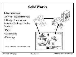
Learn about sketching with parametrics and creating feature-based models in SolidWorks. Understand the basic geometry terminology, view control, selection methods, and 2D sketch creation techniques. Enhance your design intent with intelligent sketches and geometric variables.

SolidWorks Sketching and Feature-based Modeling Guide
E N D
Presentation Transcript
SolidWorks Session 1 Ferdowsi University of Mashhad Dr. Behnam Moetakef Imani Winter 2011
SolidWorks • a feature-based, • history-based, • associative, • parametric • 3D CAD program
“Feature-based” modeling means • build the model by incrementally identifying functional shapes and applying processes to create the shapes • Many different feature types in SolidWorks enable you to create everything from the simplest geometry to more complex artistic or organic shapes. • most common features
SolidWorks is also history based • a panel to the left side of the SolidWorks window called the FeatureManager • FeatureManager keeps a list of the features in the order in which you have added them • enables you to reorder items in the tree (in effect, to change history) • the order in which you perform operations is important
1. Create a sketch. 2. Extrude the sketch. 3. Create a second sketch. 4. Extrude the second sketch. 5. Create a third sketch. 6. Extrude Cut the third sketch. 7. Apply fillets. 8. Shell the model. FeatureManager design trees
Sketching with Parametrics • Sketching is the foundation that underlies the most common feature types. • sketching in parametric software is vastly different from drawing lines in 2D CAD • SolidWorks sketches are parametric • you can create sketches that change according to certain rules, and • maintain relationships through those changes • It extends beyond sketching to all the types of geometry you can create in SolidWorks • Creating sketches and features with intelligence is the basis of the concept of Design Intent
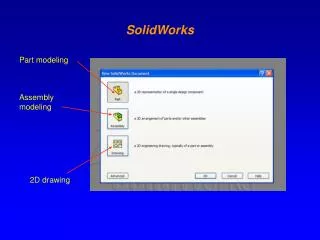
SolidWorks has three main data type files: • parts, • assemblies, and • drawings
Vertex Edge Edge Faces Terminology: Basic Geometry • Face – The surface or “skin” of a part. Faces can be flat or curved, can be analytic or parametric • Edge – The boundary of a face. Edges can be straight or curved,can be analytic or parametric • Vertex – The corner where edges meet
Terminology: Basic Geometry Face Edge Vertex Topologic Variable Geometric Variable Surface Curve Point Relations of Geometric Variables Representation of geometric Objects
View Control Magnify or reduce the view of a model in the graphics area. • Zoom to Fit – displays the part so that it fills the current window. • Zoom to Area – zooms in on a portion of the view that you select by dragging a bounding box. • Zoom In/Out – drag the pointer upward to zoom in. Drag the pointer downward to zoom out. • Zoom to Selection – the view zooms so that the selected object fills the window.
Display Modes • Illustrate the part in various display modes. Wireframe Hidden lines Visible Hidden Lines Removed Shaded Shaded Without Edges
Isometric View Top View Back View Left View Front View Right View Bottom View Standard Views
Front Right Bottom Isometric Top Left Back Normal To (selected plane or planar face) View Orientation Changes the view display to correspond to one of the standard view orientations.
View Orientation • The views most commonly used to describe a part are: • Top View • Front View • Right View • Isometric View • Viewing the model or drawing through one, two, or four viewports • Link view ?
Default Planes • Default Planes • Front, Top, and Right Correspond to the standard principle drawing views: • Front = Front or Back view • Top = Top or Bottom view • Right = Right or Left view
Isometric View • Displays the part with height, width, and depth equally foreshortened. • Pictorial rather than orthographic. • Shows all three dimensions – height, width, and depth. • Easier to visualize than orthographic views.
Selection Methods • Highlighting • Select Entity • Box Selection • Cross Selection • Invert Selection • Select Loop • Select Chain • Selection Filter • Tangent Selection
Creating a 2D Sketch • Click Sketch on the Sketch toolbar. • Select the Front plane as a sketch plane. • Click Rectangleon the Sketch Tools toolbar. • Move the pointer to the Sketch Origin.
Creating a 2D Sketch • Click the left mouse button. • Drag the pointer up and to the right. • Click the left mouse button again.
Adding Dimensions • Dimensions specify the size of the model. To create a dimension: • Click Dimension on the Sketch Relations toolbar. • Click the 2D geometry. • Click the text location. • Enter the dimension value. Text location 2D geometry
2-D Object Creation Methods 3 Point Arc Line Tangent Arc Centerpoint Arc Point Rectangle Spline Circle
2-D Objects Creation Methods Chamfer Fillet Mirror Trim Offset Entities Extend
Angular Radial Linear Dimensioning & Relations Dimensioning Relations Collinear Perpendicular Vertical Horizontal
Dimensioning & Relations Midpoint Coincident Tangent Parallel Equal Coradial Concentric Symmetric
تمرین • کلیه قیود در sketch را با رسم شکل توضیح دهید. • قطعه زیر را در SolidWorks ایجاد کنید • پیاده سازی convert entitiesو offset entities در روی صفحه مجزا و بر روی بیضی و بحث روی نتایج.