Overview of Reliability Redispatch Pilot Project - NIPPC Presentation, June 2007
260 likes | 366 Vues
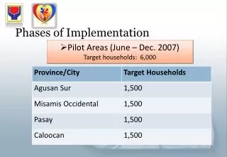
This presentation outlines the Reliability Redispatch Pilot Project for NIPPC initiated from June 26 to September 30, 2007. Key highlights include the completion of software development, operational hardware environments, and documented changes in dispatch and scheduling procedures. Training for dispatch, scheduling, and bidders is currently underway, with pilot agreement finalization on the horizon. The overview describes the bidding tool, including bid validation rules for megawatts and pricing, as well as the Power Transfer Distribution Factor (PTDF) concept vital for managing generator impacts on flowgates.

Overview of Reliability Redispatch Pilot Project - NIPPC Presentation, June 2007
E N D
Presentation Transcript
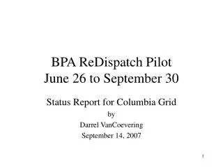
Reliability Redispatch Pilot Presentation for NIPPCJune 13, 2007 Term of Pilot 6/26/07 through 9/30/07
Project Status • Software Development complete • Hardware environments configured and operational • Dispatch and scheduling procedure changes documented • Dispatch, scheduling and bidder training underway • Pilot agreement nearing completion
Bid Tool Overview • Redispatch Bid Content • Generator • Day and Hour ending • Quantity (MW) available within 10 min. • Price per MWh • Increase (INC) and/or Decrease (DEC)
Bid Validation Rules Bid Data • INC Only Bid • DEC Only Bid • INC and DEC Bid • Neither – Zero Bid • INC Bid includes INC MW & INC Price • DEC Bid includes DEC MW & DEC Price
Bid Validation Rules Megawatts • Whole # > Zero • Not exceeding Generator’s established Maximum INC/DEC MW amount. • Not less than Generator’s established Minimum INC/DEC MW amount.
Bid Validation Rules Price • Positive U.S. currency value per MWh • Not exceeding established Maximum INC/DEC Bid Price Limit. ($400) • Not less than established Minimum INC/DEC Bid Price Limit. ($0)
Submitting a Bid • Submitted or changed up to 20 minutes prior to flow hour. • No further into the future than 5 days. (Day +5)
Calculate Redispatch Background
Introduction • A generator’s impact on a flowgate is measured by its Power Transfer Distribution Factor or PTDF. • PTDF is also known as Path Utilization Factor (PUF) and Transmission Loading Relief (TLR).
Introduction cont. • The PTDF is the ratio impact to the loading on a specific flowgate based on an increase (INC) at the generator and a like decrease (DEC) at a reference bus (Grand Coulee for our studies). • A positive PTDF will increase the loading. • A negative PTDF will decrease the loading and provide relief.
Flowgates and PTDFs/PUFs Reference Bus PUFs are zero Flowgates
Redispatch • To relieve the loading on the path, we find the pairs of generators that will provide relief. • We look for combinations of INC generator and DEC generators with a combined PTDF that is negative. • The combined PTDF is the INC PTDF – DEC PTDF. • Numbers closer to -1.0 are more effective. + -
Single Redispatch Pair JDA-CNT Redispatch: 35 MW Impact: 35*-0.508= -17.8 MW
Redispatch Solution • To get more relief, redispatch more pairs of generators. • Since a single generator could be involved in multiple pairs, the amounts are summed and each generator is called once.
Calculate Redispatch 35-MW Paul-Allston Example