Download
1 / 40
400 likes | 436 Vues
This introduction covers essential design considerations for machine components, including types of loads, stress-strain diagrams, and different stresses affecting materials. Learn about creep, fatigue, S-N curves, and endurance limits. Topics include selecting materials, analyzing loads and forces, identifying failure modes, and using design standards. Understand tensile, compressive, shear, bearing, and bending stresses, as well as torsional shear stress. Explore the concept of creep and its impact on material strength, rupture, and deformation. Improve your design skills with practical knowledge and design criteria for engineering applications.

E N D
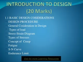
INTRODUCTION TO DESIGN(20 Marks) 1.1 BASIC DESIGN COSIDERATIONS DESIGN PROCEDURE General Cosideration in Design Types of load Stress-Strain Diagram Types of Stresses Concept of Creep Fatigue S-N Curve Endurance Limit Visit for more Learning Resources
Course Outcome • C604.1: Analyze and evaluate the loads, forces, stresses involved in components and decide the dimensions. • C604.2: Select design criteria for different machine components. • C604.3: Select proper material for machine components. • C604.4: Identify various modes of failure of machine components under different load patterns. • C604.5: Use design data book and different IS codes for design. • C604.6: Select standard components with their specifications as per design.
General Cosideration in Design • Type of load and stresses caused by the load. • Motion of the parts or kinematics of the machine. • Selection of materials. • Form and size of the parts. • Frictional resistance and lubrication. • Convenient and economical features. • Use of standard parts. • Safety of operation. • Workshop facilities. • Number of machines to be manufactured. • Cost of construction. • Assembling.
Types of load • Dead or steady load :A load is said to be a dead or steady load, when it does not change in magnitude or direction. • Live or variable load:A load is said to be a live or variable load, when it changes continually. • Suddenly applied or shock loads :A load is said to be a suddenly applied or shock load, when it is suddenly applied or removed. • Impact load :A load is said to be an impact load, when it is applied with some initial velocity.
Stress-Strain Diagram Proportional limit. Elastic limit. Yield point. Ultimate stress. Breaking stress. Perntage reduction in area. A = Original cross-sectional area. a = Cross-sectional area at the neck 7. Percentage elongation.
Types of Stresses • Tensile Stress When a body is subjected to two equal and opposite axial pulls P (also called tensile load) as shown in Fig., then the stress induced at any section of the body is known as tensile stress as shown in Fig. Tensile stress, σt =P/A Tensile strain,εt = δl/ l
Compressive Stress When a body is subjected to two equal and opposite axial pushes P (also called compressive load) as shown in Fig, then the stress induced at any section of the body is known as compressive stress as shown in Fig. Compressive stress, σc = P/A compressive strain, εc = δl /l
Shear Stress • When a body is subjected to two equal and opposite forces acting tangentially across the resisting section, as a result of which the body tends to shear off the section, then the stress induced is called shear stress • Single Shear
Double shear. • The area resisting the shear off the rivet,
Crushing Stress • A localised compressive stress at the surface of contact between two members of a machine part, that are relatively at rest is known as crushing stress
Bearing Stress • A localised compressive stress at the surface of contact between two members of a machine part, that has relative motion is known as bearing stress
Torsional Shear Stress • When a machine member is subjected to the action of two equal and opposite couples acting in parallel planes (or torque or twisting moment), then the machine member is said to be subjected to torsion. The stress set up by torsion is known as torsional shear stress. • Torsion equation:
Bending Stress • In engineering practice, the machine parts of structural members may be subjected to static or dynamic loads which cause bending stress in the sections besides other types of stresses such as tensile, compressive and shearing stresses. • The bending equation is given by
Principal Stresses and Principal Planes • Planes which have no shear stress are known as principal planes and the direct stresses along these planes are known as principal stresses. The planes on which the maximum shear stress act are known as planes of maximum shear. • When a member is subjected to bi-axial stress (i.e. direct stress in two mutually perpendicular planes accompanied by a simple shear stress), then the normal and shear stresses are obtained as discussed below:
When a member is subjected to direct stress in one plane accompanied by a simple shear stress as shown • in Fig, then the principal stresses are obtained by substituting σ2 = 0 in above equations.
Creep: When a part is subjected to a constant stress at high temperature for a long period of time, it will undergo a slow and permanent deformation called creep. This property is considered in designing internal combustion engines, boilers and turbines. • Creep Strength: It is defined as the maximum strength that the material can withstand for a specified length of time without excessive deformation. • Creep Ruptuure strength of the material is the maximum strength that the material can withstand for a specified length of time. Creep Curve
Fatigue: When a material is subjected to repeated stresses, it fails at stresses below the yield point stresses. Such type of failure of a material is known as *fatigue. The failure is caused by means of a progressive crack formation which are usually fine and of microscopic size. This property is considered in designing shafts, connecting rods, springs, gears, etc
ENDURANCE LIMIT • It may be defined as the safe maximum stress which can be applied to the machine part working under actual condition. • It is defined as maximum value of completely reversed bending stress which a polished specimen can withstand without failure for infinite number of cycles. FACTORS AFFECTING ENDURANCE STRENGTH • Load factor (KL) • Surface finish factor(KSF) • Size factor(KSZ) • Reliability factor(KR) • Miscellaneous factors(K) ns. NOTCH SENSITIVITY (q) This is defined as the degree to which the actual stress concentration effect compares with theoretical stress concentration effect.
Factor of safety • It is defined, in general, as the ratio of the maximum stress to the working stress Mathematically, ductile materials e.g. mild steel, the fos is based upon the yield point stress to the working stress. brittle materials e.g. cast iron, the fos for brittle materials is based on ultimate stress
Selection of Factor of Safety • Before selecting a proper factor of safety, a design engineer should consider the following points : • The reliability of the properties of the material and change of these properties during service ; • The reliability of test results and accuracy of application of these results to actual machine parts ; • The reliability of applied load ; • The certainty as to exact mode of failure ; • The extent of simplifying assumptions ; • The extent of localised stresses ; • The extent of initial stresses set up during manufacture ; • The extent of loss of life if failure occurs ; and • The extent of loss of property if failure occurs.
Stress Concentration • Whenever a machine component changes the shape of its cross-section, the simple stress distribution no longer holds good and the neighbourhood of the discontinuity is different. This irregularity in the stress distribution caused by abrupt changes of form is called stress concentration. • It occurs for all kinds of stresses in the presence of fillets, notches, holes, keyways, splines, surface roughness or scratches etc.
Causes • Abrupt Change of c/s • Poor surface finish • Localized loading • Variation in the material properties • Methods of Reducing Stress Concentration • Avoiding sharp corners • Providing fillets • Use of multiple holes instead of single hole. • Undercutting the shoulder part
Theoretical or Form Stress Concentration Factor • The theoretical or form stress concentration factor is defined as the ratio of the maximum stress in a member (at a notch or a fillet) to the nominal stress at the same section based upon net area. Mathematically, theoretical or form stress concentration factor, The value of Kt depends upon the material and geometry of the part.
Steels Designated on the Basis of Mechanical Properties • These steels are carbon and low alloy steels where the main criterion in the selection and inspectionof steel is the tensile strength or yield stress. According to Indian standard **IS: 1570 (Part–I)- 1978 (Reaffirmed 1993), these steels are designated by a symbol ‘Fe’ or ‘Fe E’ depending on whether • the steel has been specified on the basis of minimum tensile strength or yield strength, followed by the figure indicating the minimum tensile strength or yield stress in N/mm2. For example ‘Fe 290’ means a steel having minimum tensile strength of 290 N/mm2 and ‘Fe E 220’ means a steel having yield strength of 220 N/mm2.
Steels Designated on the Basis of Chemical Composition • According to Indian standard, IS : 1570 (Part II/Sec I)-1979 (Reaffirmed 1991), the carbon steels are designated in the following order : (a) Figure indicating 100 times the average percentage of carbon content, (b) Letter ‘C’, and (c) Figure indicating 10 times the average percentage of manganese content. • The figure after multiplying shall be rounded off to the nearest integer. • For example 20C8 means a carbon steel containing 0.15 to 0.25 per cent (0.2 per cent on an average) carbon and 0.60 to 0.90 per cent (0.75 per cent rounded off to 0.8 per cent on an average) manganese.
Free Cutting Steels • According to Indian standard, IS : 1570 (Part III)-1979 (Reaffirmed 1993), carbon and carbon manganese free cutting steels are designated in the following order : • 1. Figure indicating 100 times the average percentage of carbon, • 2. Letter ‘C’, • 3. Figure indicating 10 times the average percentage of manganese, and • 4. Symbol ‘S’ followed by the figure indicating the 100 times the average content of sulphur. • If instead of sulphur, lead (Pb) is added to make the steel free cutting, then symbol ‘Pb’ may be used
Indian Standard Designation of Low and Medium Alloy Steels • According to Indian standard, IS : 1762 (Part I)-1974 (Reaffirmed 1993), low and medium • alloy steels shall be designated in the following order : • 1. Figure indicating 100 times the average percentage carbon. • 2. Chemical symbol for alloying elements each followed by the figure for its average • percentage content multiplied by a factor as given below :
Indian Standard Designation of High Alloy Steels (Stainless Steel and Heat Resisting Steel) • According to Indian standard, IS : 1762 (Part I)-1974 (Reaffirmed 1993), the high alloy steels • (i.e. stainless steel and heat resisting steel) are designated in the following order: • 1. Letter ‘X’. • 2. Figure indicating 100 times the percentage of carbon content. • 3. Chemical symbol for alloying elements each followed by a figure for its average percentage content rounded off to the nearest integer. • 4. Chemical symbol to indicate specially added element to allow the desired properties. • For example, X 10 Cr 18 Ni 9 means alloy steel with average carbon 0.10 per cent, chromium 18 per cent and nickel 9 per cent.
Indian Standard Designation of High Speed Tool Steel • According to Indian standard, IS : 1762 (Part I)-1974 (Reaffirmed 1993), the high speed tool • steels are designated in the following order : • 1. Letter ‘XT’. • 2. Figure indicating 100 times the percentage of carbon content. • 3. Chemical symbol for alloying elements each followed by the figure for its average percentage content rounded off to the nearest integer, and • 4. Chemical symbol to indicate specially added element to attain the desired properties. • For example, XT 75 W 18 Cr 4 V 1 means a tool steel with average carbon content 0.75 percent, tungsten 18 per cent, chromium 4 per cent and vanadium 1 per cent.
Theories of Failure Under Static Load • 1. Maximum principal (or normal) stress theory (also known as Rankine’s theory). • 2. Maximum shear stress theory (also known as Guest’s or Tresca’s theory). • 3. Maximum principal (or normal) strain theory (also known as Saint Venant theory). • 4. Maximum strain energy theory (also known as Haigh’s theory). • 5. Maximum distortion energy theory (also known as Hencky and Von Mises theory).
Maximum Principal or Normal Stress Theory (Rankine’s Theory) • According to this theory, the failure or yielding occurs at a point in a member when the maximum principal or normal stress in a bi-axial stress system reaches the limiting strength of the material in simple tension test. • Since the limiting strength for ductile materials is yield point stress and for brittle materials(which do not have well defined yield point) the limiting strength is ultimate stress, therefore according to the above theory, taking factor of safety (F.S.) into consideration, the maximum principal or normal stress (σt1) in a bi-axial stress system is given by
Maximum Shear Stress Theory (Guest’s or Tresca’s Theory) According to this theory, the failure or yielding occurs at a point in a member when the maximum shear stress in a bi-axial stress system reaches a value equal to the shear stress at yield point in a simple tension test. Mathematically, τmax = τyt /F.S. ...(i) where τmax = Maximum shear stress in a bi-axial stress system, τyt = Shear stress at yield point as determined from simple tension test, and F.S. = Factor of safety. Maximum Distortion Energy Theory (Hencky and Von Mises Theory) According to this theory, the failure or yielding occurs at a point in a member when the distortion strain energy (also called shear strain energy) per unit volume in a bi-axial stress system reaches the limiting distortion energy (i.e. distortion energy at yield point) per unit volume as determined from a simple tension test. Mathematically, the maximum distortion energy theory for yielding is expressed as (σt1)2 + (σt2)2 – 2σt1 × σt2 = . For more detail contact us