Download
1 / 32
330 likes | 365 Vues
This chapter explores the propagation of electromagnetic waves in free space, lossy dielectrics, lossless dielectrics, and conducting media. It discusses reflection phenomena at interfaces and derives Maxwell's equations for plane waves.

E N D
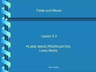
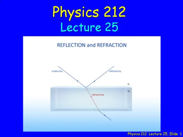
CHAPTER 10 PROPAGATION & REFLECTION OF PLANE WAVES 10.0 PROPAGATION & REFLECTION OF PLANE WAVES 10.1 ELECTRIC AND MAGNETIC FIELDS FOR PLANE WAVE 10.2 PLANE WAVE IN LOSSY DIELECTRICS – IMPERFECT DIELECTRICS 10.3 PLANE WAVE IN LOSSLESS (PERFECT) DIELECTRICS 10.4 PLANE WAVE IN FREE SPACE 10.5 PLANE WAVE IN CONDUCTORS 10.6 POWER AND THE POYNTING VECTOR
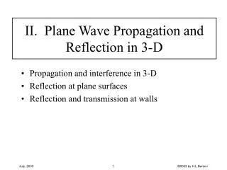
10.0 PROPAGATION & REFLECTION OF PLANE WAVES Will discuss the effect of propagation of EM wave in four medium : Free space ; Lossy dielectric ; Lossless dielectric (perfect dielectric) and Conducting media. Also will be discussed the phenomena of reflections at interface between different media. Ex : EM wave is radio wave, TV signal, radar radiation and optical wave in optical fiber. Three basics characteristics of EM wave : • travel at high velocity • - travel following EM wave characteristics • - travel outward from the source These propagation phenomena for a type traveling wave called plane wave can be explained or derived by Maxwell’s equations.
From Maxwell’s equations : 10.1 ELECTRIC AND MAGNETIC FIELDS FOR PLANE WAVE
Assume the medium is free of charge : From vector identity and taking the curl of (1)and substituting (1) and (2)
Similarly in the same way, from vector identity and taking the curl of (2)and substituting (1) and (2) In Cartesian coordinates : • Assume that : • Electric field only has x component • Propagate in the z direction
The solution for this equation : Incidence wave propagate in +z direction Reflected wave propagate in -z direction To find H field :
On the right side equation : Equating components on both side = y component
Hence : These equations of EM wave are called PLANE WAVE. • Main characteristics of EM wave : • Electric field and magnetic field always perpendicular. • NO electric or magnetic fields component in the direction of propagation. • will provides information on the direction of propagation.
10.2 PLANE WAVE IN LOSSY DIELECTRICS – IMPERFECT DIELECTRICS Assume a media is charged free , ρv =0 (1) (2) Taking the curl of (2) :
(1) (2) From vector identity : Equating (4) and (5) for Re and Im parts : Where : (4) Define : (5)
Magnitude for (5) ; Add (10) and (6) : Hence : Magnitude for (4) ; Equate (8) and (9) : is known as attenuation constant as a measure of the wave is attenuated while traveling in a medium.
If the electric field propagate in +z direction and has component x, the equation of the wave is given by : And the magnetic field : Substract (10) and (6) : is phase constant (13) (14)
(14) (15) Conclusions that can be made for the wave propagating in lossy dielectrics material : (i) E and H fields amplitude will be attenuated by (ii) E leading H by where ; (15) Intrinsic impedance : (16) where ; (17)
Loss tangent ; Loss tangent values will determine types of media : tan θ small (σ / ωε < 0.1) – good dielectric – low loss tan θ large (σ /ωε > 10 ) - good conductor – high loss Wave velocity ; From (17) and (18) (18) Another factor that determined the characteristic of the media is operating frequency. A medium can be regarded as a good conductor at low frequency might be a good dielectric at higher frequency.
(14) (15) x z y Graphical representation of E field in lossy dielectric
10.3 PLANE WAVE IN LOSSLESS (PERFECT) DIELECTRICS Characteristics: (19) Substitute in (11) and (12) : (20) (21) (22) The zero angle means that E and H fields are in phase at each fixed location.
Free space is nothing more than the perfect dielectric media : Characteristics: (23) (20) Substitute in (20) and (21) : (21) (24) (22) (25) where (26) 10.4 PLANE WAVE IN FREE SPACE
(14) (15) x Generally : Ex+ kos(-z) z (at t = 0) Hy+ kos(-z) y The field equations for E and H obtained : (27) (28) E and H fields and the direction of propagation :
In conductors : or (29) With the characteristics : Substitute in (11 and (12) : (30) E leads H by 450 (31) The field equations for E and H obtained : (32) (33) 10.5 PLANE WAVE IN CONDUCTORS
From the diagram is referred to as the skin depth. It refers to the amplitude of the wave propagate to a conducting media is reduced to e-1 or 37% from its initial value. It can be seen that at higher frequencies is decreasing. x E0 0.368E0 z It is seen that in conductors and waves are attenuated by In a distance : (34)
Find and . From intrinsic impedance, the magnitude of E field : It is seen that E field leads H field : Ex.10.1 : A lossy dielectric has an intrinsic impedance of at the particular frequency. If at that particular frequency a plane wave that propagate in a medium has a magnetic field given by : Solution : Hence :
; and we know To find : Hence:
(39) (35) (36) Dot product (36) with : (37) From vector identity: (38) Change in (37) and use (38) , equation (37) becomes : 10.6 POWER AND THE POYNTING VECTOR
(39) (35) where: (42) And from (35): (40) Therefore (39) becomes: (41) Integration (41) throughout volume v :
(42) Using divergence theorem to (42): Dissipated ohmic power The decrease of the energy densities of energy stored in the electric and magnetic fields Total energy flow leaving the volume Equation (43) shows Poynting Theorem and can be written as :
Output power Ohmic losses Stored magnetic field Stored electric field Input power Poynting theorem states that the total power flow leaving the volume is equal to the decrease of the energy densities of energy stored in the electric and magnetic fields andthe dissipated ohmic power. The theorem can be explained as shown in the diagram below :
Given for lossless dielectric, the electric and magnetic fields are : The Poynting vector becomes:
To find average power density : Integrate Poynting vector and divide with interval T = 1/f : Average power through area S :
Given for lossy dielectric, the electric and magnetic fields are : The Poynting vector becomes: Average power :
Ex.10.2: A uniform plane wave propagate in a lossless dielectric in the +z direction. The electric field is given by : The average power density measured was . Find: • Dielectric constant of the material if • Wave frequency • Magnetic field equation Solution: (i) Average power :
For lossless dielectric : (ii) Wave frequency :