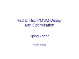
PMSM Design
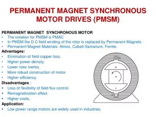
PMSM Design. Liping Zheng 06/06/2003. PMSM Configuration. Litz-wire: 1.78 mm x 2.27 mm 50 strands @ AWG 30 Gap : 0.5 mm Stator Di: 25.5 mm Do: 38 mm Length: 25.4 mm Shaft diameter: 16 mm. No major shaft stress problem if we select high stress shaft material.

PMSM Design
E N D
Presentation Transcript
PMSM Design Liping Zheng 06/06/2003
PMSM Configuration Litz-wire: 1.78 mm x 2.27 mm 50 strands @ AWG 30 Gap : 0.5 mm Stator Di: 25.5 mm Do: 38 mm Length: 25.4 mm Shaft diameter: 16 mm No major shaft stress problem if we select high stress shaft material. We’ve sent out the purchase requisition form to the university.
PMSM Loss Motor Efficiency: Control Efficiency: Total Efficiency:
Other Possible Loss (I) • Copper loss associated with eddy current. • Skin depth : • Litz-wire : 50 @ AWG 30 (D=0.01 in or 0.25 mm) • Eddy current can be ignored. • Copper loss associated with the airgap flux leakage. • Twisted Litz-wire can greatly reduce the loss. Twisting pitch is the same as the motor active length.
Other Possible Loss (II) • Loss in the shaft. • Slotless stator can reduce this loss greatly. • Loss in the permanent magnet. • Slotless stator can reduce this loss greatly. • Loss due to nonideal control • Loss associated with non ideal control. • Loss associated with current harmonics. • Loss of the low pass filter.
Verify Stator Core Loss Using FEM Simulation • Two methods to get the stator core loss: • Based on the frequency and flux density vs. Loss curve. • Based on finite element method (FEM) simulation.
45W/lb Stator Material (Arnon 5) - Loss Core loss= 10.4 W
Core Loss Using FEM • At a given frequency, the iron loss for electrical steel can be calculated from: Where Kh is the hysteresis coefficient. Kc is the classical eddy coefficient. Ke is the excess eddy current coefficient. F is the frequency. Above coefficients can be calculated by the curve fitting of the manufacturer’s loss data sheet.
Unit Setup Executive Parameters Curve Fitting Results:
Stator Core Loss of the PMSM Core loss is 9.5W
Stator Core Loss of Current or PM Only Winding mmf contributes only smaller portion of the core loss
Further Work • Estimate the loss in the shaft. • Estimate the loss in the permanent magnet. • Simulation the loss of the low pass inductors. • Optimize the shaft structure.