Download

1 / 26
260 likes | 543 Vues
參考文獻 :IEEE TRANSACTIONS ON INDUSTRY APPLICATIONS, VOL. 44, NO. 5, SEPTEMBER/OCTOBER 2008 作 者 :Antti Piippo, Janne Salomäki, Member, IEEE, and Jorma Luomi, Member, IEEE. Signal Injection in Sensorless PMSM Drives Equipped With Inverter Output Filter. 指導教授 : 王明賢 報 告 人 : 吳烱華

E N D
參考文獻:IEEE TRANSACTIONS ON INDUSTRY APPLICATIONS, VOL. 44, NO. 5, SEPTEMBER/OCTOBER 2008 作 者:Antti Piippo, Janne Salomäki, Member, IEEE, and Jorma Luomi, Member, IEEE Signal Injection in Sensorless PMSM DrivesEquipped With Inverter Output Filter 指導教授:王明賢 報 告 人:吳烱華 報告日期:2010.12.24
Agenda • I. INTRODUCTION • II. FILTER AND MOTOR MODELS • III. CONTROL SYSTEM • IV. OBSERVER STRUCTURE • V. RESULTS • VI. CONCLUSION
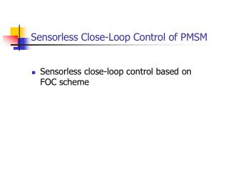
Abstract This paper proposes a hybrid observer for sensorless control of PMSM drives equipped with an inverter output LC filter. An adaptive full-order observer is augmented with a high-frequency signal injection method at low speeds. The only measured quantities are the inverter phase currents and the dc-link voltage. The effects of the LC filter ont he signal injection are investigated, and it is shown that the filter is not an obstacle to using signal injection methods. The proposed method allows sensorless operation in a wide speed range down to zero speed.
INTRODUCTION PROBLEMS MAY be encountered in ac motor drives due to the nonsinusoidal voltage produced by a pulsewidthmodulated inverter. The high rate of change of the voltage (i.e., high du/dt) may cause excessive voltage stresses in the stator winding insulations. It may also cause leakage currents through the parasitic capacitances of the stator winding and produce bearing currents. Voltage harmonics cause acoustic noise and power losses; the losses caused by eddy currents are a special concern in high-speed solid-rotor motors.
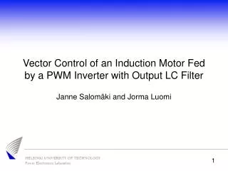
A common approach to overcome these problems is to use an inverter output filter [1]–[4]. An LC filter, having the resonance frequency below the switching frequency, is a typical choice for the filter topology if a nearly sinusoidal output voltage is required. However, this kind of heavy filtering makes the motor control more difficult. A conventional scalar control method is usually employed, but when better control performance is needed, a vector control method must be used.For vector control, the filter dynamics should be taken into account.
In this paper, a hybrid observer is proposed, where a speed-adaptive full-order observer [10] is augmented with a pulsating HF signal injection technique at low speeds. The effect of the inverter output LC filter on the signal injection is investigated, and the problems caused by the filter on the signal injection are addressed. It is shown that signal injection methods are feasible even with the filter if the frequency of the injected voltage signal is suitably chosen. For the compatibility of the signal injection method, the dynamics of the system are analyzed in frequency domain. The validity of the proposed hybrid observer is shown by means of simulations and Laboratory experiments.
FILTER AND MOTOR MODELS Fig. 1 shows a PMSM drive system equipped with an LCfilter. The inverter output voltage uA is filtered by the LC filter,resulting in a nearly sinusoidal stator voltage us. The inverteroutput current iA and the dc-link voltage udc are the only measured quantities.
The PMSM and the LC filter are modeled in the d − qreference frame fixed to the rotor. The d-axis is oriented alongthe permanent-magnet flux, whose angle in the stator referenceframe is θm in electrical radians. The stator voltage equation is where us = [usd usq]T is the stator voltage, is = [isd isq]Tis the stator current, ψs = [ψsd ψsq]T is the stator flux, Rs isthe stator resistance, ωm = θ˙m is the electrical angular speed ofthe rotor, and
The stator flux is where ψpm = [ψpm 0]T is the permanent-magnet flux and is the inductance matrix, with Ld and Lq being the direct- and quadrature-axis inductances, respectively. The electromagnetic torque is given by where p is the number of pole pairs.
The LC filter equations are where iA = [iAd iAq]T is the inverter current, uA =[uAd uAq]T is the inverter output voltage, Lf is the inductance,RLf is the series resistance of the filter inductor,and Cf is the filter capacitance.
CONTROL SYSTEM Fig. 2 shows a simplified block diagram of the control system(with the estimated quantities being marked by the symbolˆ).The cascade control and the speed- adaptive full-order observerare implemented in the estimated rotor reference frame. Theestimated rotor position ˆθm is obtained by integrating ˆωm. Theinverter current, the stator voltage, and the stator current arecontrolled by PI controllers, and cross- couplings due to therotating reference frame are compensated [7]. A maximum torque per current method is used for calculating the statorcurrent reference [15]. The rotor speed is governed by a PIcontroller with active damping.
Fig. 2. Simplified block diagram of the control system. Double lines indicate vector quantities, whereas single lines indicate scalar quantities. Vector quantitieson the left-hand side of coordinate transformations are in the estimated rotor reference frame, whereas those on the right-hand side are in the stator referenceframe. The speed control includes the calculation of the stator current reference according to the maximum torque per current method.
OBSERVER STRUCTURE In the following, the speed-adaptive full-order observer proposedin [10] is augmented with an HF signal injection techniqueto stabilize the observer at low speeds. The two methodsare combined in a fashion similar to [16]. The observer gain ismodified for better compatibility with the HF signal Injectionmethod. A. HF Signal Injection B. Effect of the Filter on Signal Injection C. Speed-Adaptive Full-Order Observer
A. HF Signal Injection In this paper, an adaptive full-order observer is primarily used for the estimation. The HF signal injection method is used for a correction in the observer, and for that purpose, an error signal proportional to the rotor position estimation error is required.Alternating signal injection is preferred to rotating signal injection since the resulting HF torque ripple is lower. Demodulation of the current signal is chosen because it gives the best sensitivity in the case of the motor used in the experiments.
B. Effect of the Filter on Signal Injection To illustrate the effect of the filter on the HF signal injection, frequency responses of the system were calculated numerically.Parameters given in Table I were used for this example. The inverter d-axis current response to the inverter d-axis voltage is shown in Fig. 3(a) for the rotor position estimation error ˜θm = 10◦. The amplitude response has a notch at the parallel resonance frequency of the filter capacitor and the stator inductance, and a peak at the LC filter resonance frequency.Above the frequency f ≈ 500 Hz, the LC filter amplifies the response as compared to the response obtained for the PMSM without the filter.
C. Speed-Adaptive Full-Order Observer The adaptive full-order observer is based on the dynamic models of the PMSM and the LC filter. The inverter current serves as the feedback signal for the observer, and the electrical angular speed of the rotor is estimated using an adaptation mechanism. The stator flux is selected as the state variable representing the electrical dynamics of the motor by inserting the stator current solved from (2) into (1). When the dynamic equations of the filter are included, the observer is defined by
where ˆx = [ˆiTA ˆuTsˆψTs ]T. The inverter voltage uA and the permanent-magnet flux estimate ˆψpm are considered as inputs to the system. The system matrices and the observer gain matrix in (10) are respectively, where I is the 2 × 2 unit matrix.
RESULTS The MATLAB/Simulink environment was used for the simulations.The parameter values used in the controller were equal to those of the motor and filter models. Simulation and experimental results showing speed reference steps at zero load torque are shown in Fig. 6. The rotor position estimation error shown in the last subplot is the difference between the actual (measured) and estimated values. This position estimation error is a good indicator of the estimation performance. The HF signal injection contributes to the rotor speed and position estimation at the speed ωm = 0.05 p. u. The estimation accuracy for the rotor speed and position is good even at low speeds. The ripple in the measured results is caused by harmonics in the permanent-magnet flux and in the motor inductances [20], and current measurement inaccuracies.
Fig. 6. Speed reference steps at no load. (a) Simulation results. (b) Experimental results. The first subplot shows (solid) the electrical angular speed, (dashed) its estimate, and (dotted) its reference. The second subplot shows (solid) the estimated electromagnetic torque and (dotted) load torque reference. The last subplot shows the estimation error of rotor position in electrical degrees.
Fig. 7 shows simulation and experimental results at zerospeed reference when nominal load torque steps are applied. The proposed observer is stable in both transient and steady state conditions. The rotor position estimation error stays small, indicating good dynamic properties. The steady-state rotor position estimation error is caused by spatial harmonics in the stator inductances [20]. This estimation error is a periodic function of the rotor position. Experimental results showing a slow speed reversal at nominal load torque are shown in Fig. 8. The system is stable in both the motoring and regenerating modes of operation, and sustained operation at low speeds is possible.
Fig. 7. Load torque steps at zero-speed reference. (a) Simulation results. (b) Experimental results. Explanations of the curves are as in Fig. 6.
Fig. 8. Experimental results showing slow speed reversal at nominal load torque. The first subplot shows (solid) the electrical angular speed, (dashed) its estimate, and (dotted) its reference. The second subplot shows the estimated stator d-axis current, and the third subplot shows the estimated stator q-axis current. The last subplot shows the estimation error of rotor position in electrical degrees.
CONCLUSION It is possible to use a signal injection method for the rotor speed and position estimation of PMSM drives even if an inverter output LC filter is used. According to the frequency domain analysis shown in this paper, the excitation frequency of the signal injection should be selected carefully in order to avoid exciting the filter resonance. The signal injection method is used for augmenting an adaptive full-order observer at low speeds. The simulation and experimental results show that the proposed system can cope with stepwise changes in the speed reference and load torque. The performance of the proposed sensorless method is comparable to that of a PMSM drive without the LC filter.
REFERENCES [1] Y. Murai, T. Kubota, and Y. Kawase, “Leakage current reduction for a high-frequency carrier inverter feeding an induction motor,” IEEE Trans. Ind. Appl., vol. 28, no. 4, pp. 858–863, Jul./Aug. 1992. [2] M. Carpita, D. Colombo, A. Monti, and A. Fradilli, “Power converter filtering techniques design for very high speed drive systems,” in Proc. EPE, Graz, Austria, Aug. 2001, CD-ROM. [3] T. D. Batzel and K. Y. Lee, “Electric propulsion with sensorless permanent magnet synchronous motor: Implementation and performance,” IEEE Trans. Energy Convers., vol. 20, no. 3, pp. 575–583, Sep. 2005. [4] J.-D. Park, C. Khalizadeh, and H. Hofmann, “Design and control of high-speed solid-rotor synchronous reluctance drive with three-phase LC filter,” in Conf. Rec. IEEE IAS Annu. Meeting, Hong Kong, Oct. 2005, pp. 715–722. [5] W. Zimmermann, “Feldorientiert geregelter Umrichterantrieb mit sinusförmigen Maschinenspannungen,” etzArchiv, vol. 10, no. 8, pp. 259–266, Aug. 1988. [6] M. Kojima, K. Hirabayashi, Y. Kawabata, E. C. Ejiogu, and T. Kawabata, “Novel vector control system using deadbeat-controlled PWM inverter with output LC filter,” IEEE Trans. Ind. Appl., vol. 40, no. 1, pp. 162– 169, Jan./Feb. 2004. [7] J. Salomäki and J. Luomi, “Vector control of an induction motor fed by a PWM inverter with output LC filter,” EPE J., vol. 16, no. 1, pp. 37–43, Jan.–Mar. 2006.
[8] J. Salomäki, M. Hinkkanen, and J. Luomi, “Sensorless vector control of an induction motor fed by a PWM inverter through an output LC filter,” Trans. Inst. Electr. Eng. Jpn., vol. 126-D, no. 4, pp. 430–437, Apr. 2006. [9] J. Salomäki, M. Hinkkanen, and J. Luomi, “Sensorless control of induction motor drives equipped with inverter output filter,” IEEE Trans. Ind. Electron., vol. 53, no. 4, pp. 1188–1197, Aug. 2006. [10] J. Salomäki, A. Piippo, M. Hinkkanen, and J. Luomi, “Sensorless vector control of PMSM drives equipped with inverter output filter,” in Proc. IEEE IECON, Paris, France, Nov. 2006, pp. 1059–1064. [11] M. Schroedl, “Sensorless control of AC machines at low speed and standstill based on the INFORM method,” in Conf. Rec. IEEE IAS Annu. Meeting, San Diego, CA, Oct. 1996, vol. 1, pp. 270–277. [12] P. L. Jansen and R. D. Lorenz, “Transducerless position and velocity estimation in induction and salient AC machines,” IEEE Trans. Ind. Appl., vol. 31, no. 2, pp. 240–247, Mar./Apr. 1995. [13] A. Consoli, G. Scarcella, and A. Testa, “Industry application of zero-speed sensorless control techniques for PM synchronous motors,” IEEE Trans. Ind. Appl., vol. 37, no. 2, pp. 513–521, Mar./Apr. 2001. [14] J. I. Ha, K. Ide, T. Sawa, and S. K. Sul, “Sensorless rotor position estimation of an interior permanent-magnet motor from initial states,” IEEE Trans. Ind. Appl., vol. 39, no. 3, pp. 761–767, May/Jun. 2003