Download
1 / 11
170 likes | 564 Vues
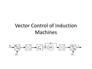
Vector Control of an Induction Motor Fed by a PWM Inverter with Output LC Filter. Janne Salomäki and Jorma Luomi. Contents. Introduction Filter and motor models Cascade control system Full-order observer Results Conclusion. Introduction.

E N D
Vector Control of an Induction Motor Fed by a PWM Inverter with Output LC Filter Janne Salomäki and Jorma Luomi
Contents • Introduction • Filter and motor models • Cascade control system • Full-order observer • Results • Conclusion
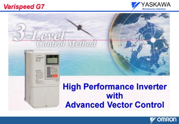
Introduction • The output voltage of a PWM inverter consists of rectangular voltage pulses • An LC output filter provides motor friendly voltage, but the control of the system becomes more difficult • The paper presents a vector control method that does not need additional measurements
Filter and motor models L i u f s dc IM w m i A C u f s
Cascade control system • Measurements needed: inverter current,DC link voltage and rotor speed
Full-order observer • Estimated rotor flux reference frame • The observer gain selection: • pole placement • constant gain • Symmetric Euler discretization
Full-order observer (2) • Observer poles with constant gain magnification
Experimental results • Experiments were made with 2.2-kW four-pole induction motor (400 V, 50 Hz) • The cutoff frequency of the LC filter was 566 Hz
Experimental results (2) Inverter voltage Stator voltage Inverter current Stator current
Experimental results (3) Measured Reference Measured Reference Reference Estimated
Conclusion • When the inverter output voltage is filtered by an LC filter, the vector control of the induction motor can be based on nested control loops • As the system states are estimated, the only required measurements are the inverter current, DC link voltage and rotor speed • Simulation and experimental results show that the proposed method works properly