Download
1 / 31
310 likes | 865 Vues
500W Three Phase Inverter As an induction motor drive. ECE 345 Presentation April 30, 2003 Team Members: Dane Barhoover Brett Nee Paulus Yulianto. Motivation. Motors account for approximately 64% of the U.S. electrical use

E N D
500W Three Phase InverterAs an induction motor drive ECE 345 Presentation April 30, 2003 Team Members: Dane Barhoover Brett Nee Paulus Yulianto
Motivation • Motors account for approximately 64% of the U.S. electrical use • Approximately 1 billion motors in the U.S. use over 1700 billion kWh/yr • 90% of the motors are less than 1 hp in size, and account for approximately 10% of the electricity consumed by the motor population • This translates to 170 billion kWh/yr
Motivation • Each 1% Improvement in Motor and Drive Efficiency Results in : • 17 billion kWh/yr of energy saved • Over $1 billion energy cost saved/yr • An equivalent of 6 –10 million tons of displaced coal/yr • 15 – 20 million tons less CO2 released into atmosphere/year
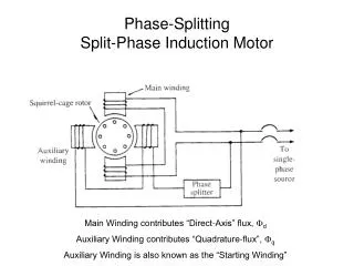
Specifications • Speed: 150RPM to 5000RPM • Shaft Load: 50W to 500W @ 1500RPM • Efficiency > 70% • Three Phase Sinusoidal current to drive an induction machine • Low Cost
Hexbridge A, B and C represent the three phase outputs to the motor
Switch Selection • Minimum ratings • 400V, 10A device • Cost • IGBT (600 V, 15A) = $1.70 (1000 qty) • MOSFET (400V, 10A) = $0.96 (1000 qty) • IGBT vs. MOSFET IGBT : Vsat = 1.80 V Requiv = 0.07 Ω FET : RDS(on) = 0.27 Ω
Switch Selection • MOSFET: FQP17N40 • Low cost • Better performance at operating current
Gate Drive • Interfaces the switching signals to the Hexbridge • Concerns: • Dead time • To prevent shoot through • Occasionally requires external circuitry to implement • Cost • Hexbridge requires six gate drive circuits • Single hex-gate drive IC: IR21362 : $4.62 (1000 qty.) • A single gate drive IC: IR2121, $1.75 (1000qty) • Keep the component count low
Gate Drive Selection • Single IC solution: IR21362 • Provides six integrated gate drives on the IC • Complementary Inputs for switching signal • Takes 3.3V logic input • Built in dead time to prevent shoot through (200ns) • Over current protection • Fault Clearing with RC time const • Enable pin to shut off gate drive
Methods for Signal Generation • Space Vector PWM • Good dynamic performance • Higher switching frequency ~20kHz • Usually uses a control loop, increasing part count and complexity • Sine-Triangle PWM • Higher switching frequency ~20kHz • Straightforward to implement • Poor dynamic performance without a control loop
Methods for Signal Generation • Harmonic Elimination • Low switching frequency • Depends on the number of harmonics eliminated • Switching frequency = (n+2)*fundamental n = last harmonic eliminated • Reduces the switching loss considerably • Difficult to derive switching waveform • Reduces switching frequency to audible range
Harmonic Elimination • Theory: • Take a square wave with 50% duty cycle and add or subtract subsequent square waves with varying duty cycles to eliminate harmonics • Even harmonics are canceled due to waveform symmetry • Triple (3*n) harmonics are eliminated in current due to balanced three-phase wye-connected load • This results in solving the following transcendental equations:
Harmonic Elimination Equations • 3rd – 9th harmonics eliminated • Each additional harmonic eliminated results in another equation and has another term in each equation • Solved using a Newton-Raphson approach implemented in MATLAB
Switching Function Implementation DSP: TMS320F2812 • Cost $25 (1000 qty) • Four independent timers • Fast Clock (150 MHz) • 6 PWM outputs • 16 channel 12 bit A/D converter
Sine-Triangle PWM • ADC reads speed command • Speed command determines the rate theta is integrated, which changes the fundamental frequency • Compute for modulation depth from speed command (m) by keeping constant V/Hz ratio • Evaluate K + m*sin(θ+α) • Load values into PWM compare registers • Triangle generated by Timer1 counter at 20kHz
Harmonic Elimination • Switching angles, modulation depth and window are stored in a look-up table • ADC reads speed command • Speed command determines the rate of progression through the look-up table as well as the modulation depth, keeping V/Hz constant • Harmonics eliminated: 3,5,7,9… 31
Implementation issues • Large look-up tables ~20k • Programming Flash • Accessing ISR through Flash • ADC noise and filtering
Arbitrary Waveform Generators • Used the Agilent 332508 • Able to construct Harmonic elimination waveforms with use of a MATLAB script • Allowed for testing while DSP code was in development
Harmonic Elimination Waveforms 350 W Load at 1500 RPM
Harmonic Elimination Waveforms 350 W Load at 1500 RPM
Efficiency Results • Results obtained at 1500RPM • Shaft load varied from 50W to 500W
Speed Control • A 0-3V command was used to adjust the speed with the DSP setup • Speed control has been verified at no load conditions for a range 150RPM to 3800RPM • Any speed greater that 3800RPM was unsafe with the test setup
Summary • Inverter has very high efficiency (~97%) • Harmonics Elimination proved very successful in removing specified harmonics • Theoretically up to 5000 RPM can be achieved with our DSP code • Continuing DSP code development for Harmonics Elimination for FEC